Powder sticking machine

A technology of sticking powder and racks, which is applied in the field of automatic greeting card production equipment, can solve problems such as low efficiency and impact on health, and achieve high efficiency

Pending Publication Date: 2019-04-09
星光印刷(苏州)有限公司
View PDF0 Cites 0 Cited by
  • Summary
  • Abstract
  • Description
  • Claims
  • Application Information

AI Technical Summary

Problems solved by technology

[0002] At present, in the production process of greeting cards, it is necessary to stick powder (i.e. stick glitter powder) to the greeting card. The existing powder sticking operation is mainly done by powder spreader, which has low efficiency, and operators are exposed to dust environment for a long time , can easily affect the health of the

Method used


Image

  • Powder sticking machine
  • Powder sticking machine
  • Powder sticking machine

Examples


Embodiment Construction

[0014] The present invention will be further described below in conjunction with the description of the drawings and specific embodiments.

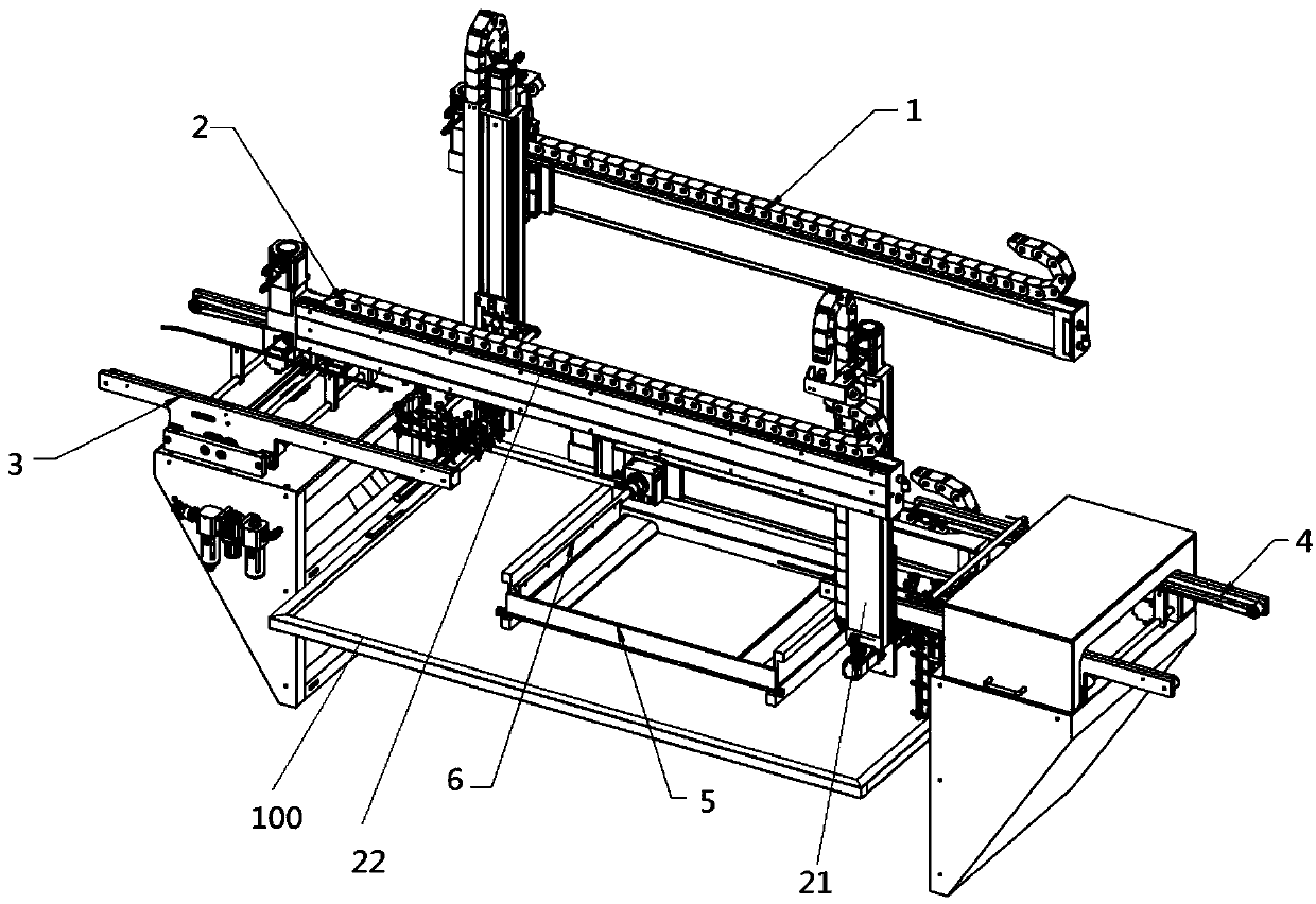
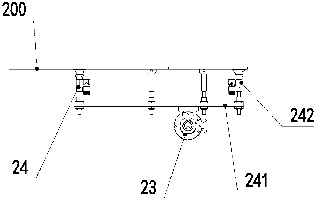
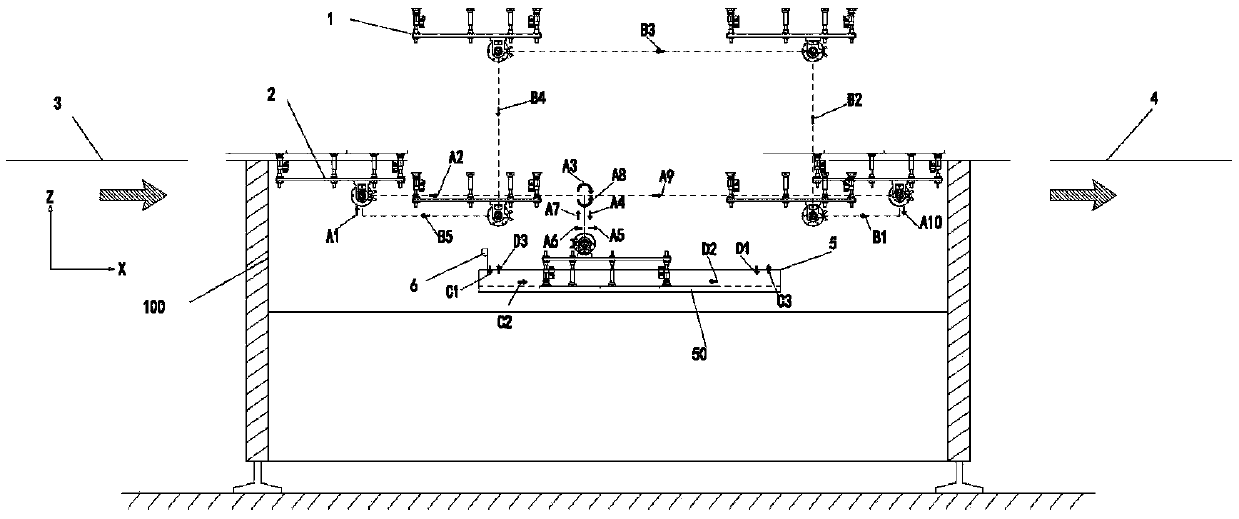
[0015] Such as Figure 1 to Figure 3 As shown, a powder sticking machine includes a frame 100, an XZR manipulator, an inlet width-adjusting conveyor belt 3, an outlet width-adjusting conveyor belt 4, a powder pool 5 and a powder pulling assembly 6, wherein there are two XZR manipulators, They are the front XZR manipulator 2 and the rear XZR manipulator 1 respectively, and the front XZR manipulator 2 and the rear XZR manipulator 1 are arranged on the frame 100 in parallel front and back, and are used to work alternately to improve the powder sticking efficiency.

[0016] Such as Figure 1 to Figure 3 As shown, the front XZR manipulator 2, the rear XZR manipulator 1, the inlet width-adjusting conveyor belt 3, the outlet width-adjusting conveyor belt 4, the powder pool 5 and the powder pulling assembly 6 are respectively arranged on the fra...


PUM


Abstract

The invention provides a powder sticking machine. The powder sticking machine comprises a machine frame, an XZR manipulator, an inlet width adjustment conveyor belt, an outlet width adjustment conveyor belt, a powder pool and a powder pulling assembly, the XZR manipulator, the inlet width adjustment conveyor belt, the outlet width adjustment conveyor belt, the powder pool and the powder pulling assembly are arranged on the machine frame, and the inlet width adjustment conveyor belt and the outlet width adjustment conveyor belt are arranged on the left and right sides of the machine frame respectively; and the powder pool and the powder pulling assembly are located between the inlet width adjustment conveyor belt and the outlet width adjustment conveyor belt, the powder pulling assembly isarranged above the powder pool, the XZR manipulator transports a greeting card from the inlet width adjustment conveyor belt into the powder pool for powder sticking, and then the greeting card is then transported from the powder pool to the outlet width adjustment conveyor belt. The powder sticking machine has the beneficial effects that the greeting card can be transported from the inlet width adjustment conveyor belt to the powder pool through the front XZR manipulator for powder sticking, the efficiency is higher, the operator does not need to be exposed to the dust environment, and the health of the body cannot be affected.

Description

technical field [0001] The invention relates to automatic production equipment for greeting cards, in particular to a powder sticking machine. Background technique [0002] At present, in the production process of greeting cards, it is necessary to stick powder (i.e. stick glitter powder) to the greeting card. The existing powder sticking operation is mainly done by powder spreader, which has low efficiency, and operators are exposed to dust environment for a long time , can easily affect the health of the body. Contents of the invention [0003] In order to solve the problems in the prior art, the invention provides a powder sticking machine. [0004] The invention provides a powder sticking machine, which includes a frame, an XZR manipulator, an inlet width-adjusting conveyor belt, an outlet width-adjusting conveyor belt, a powder pool and a powder pulling assembly, wherein the XZR manipulator, an inlet width-adjusting conveyor belt, an outlet The width-adjusting conve...

Claims


Application Information

Patent Timeline
IPC IPC(8): B65G47/248B65G47/91B42D15/02B42D15/04
CPCB65G47/248B65G47/914B42D15/02B42D15/04
Inventor 连家良冯元瑜张剑辉梁军明徐慧超
Owner 星光印刷(苏州)有限公司
Why Eureka
Try Eureka