
Automatically-overturning clamping device for wind power blades

An automatic flipping and clamping device technology, which is applied in the direction of transportation and packaging, conveyor objects, etc., can solve the problems of easy damage to the electric cylinder, large design size, difficult handling, etc., and achieve perfect blade fitting and clamping mechanism, Good universal effect

Active Publication Date: 2019-04-09
HEBEI UNIV OF TECH
View PDF12 Cites 7 Cited by
  • Summary
  • Abstract
  • Description
  • Claims
  • Application Information

AI Technical Summary

Problems solved by technology

In addition, due to the huge volume of the blades, it is extremely difficult to carry them.
Nowadays, the handling operation of blades is mostly hoisting and handling, which is time-consuming and laborious. However, it is difficult for traditional small clamping and handling equipment to complete such a large amount of work.
[0004] Aiming at the above problems, such as the Chinese invention patent (CN 104891226 A) has announced a wind power blade turning device, the metal swivel of the device is not installed on both sides of the rotating disc guide mechanism, which makes the turning motion of the metal swivel unstable; in addition, the device The internal structure of the metal swivel is complex. In addition to welding multiple mounting plates and beams, there are also multiple groups of electric cylinders installed symmetrically to clamp the blades. Due to the large working space required by the electric cylinders, and the The volume of the blade to be clamped is huge, which makes the overall design size of the device large and complex in structure; finally, the electric cylinder is generally only used to bear the push-pull force, but cannot bear the shear force, so when the metal swivel of the device is turned over, The electric cylinder is easily damaged due to the huge shear force exerted by the blades, resulting in unpredictable engineering hazards

Method used


Image

  • Automatically-overturning clamping device for wind power blades
  • Automatically-overturning clamping device for wind power blades
  • Automatically-overturning clamping device for wind power blades

Examples


Embodiment Construction

[0034] Specific examples of the present invention are given below. The specific embodiments are only used to further describe the present invention in detail, and do not limit the protection scope of the claims of the present application.

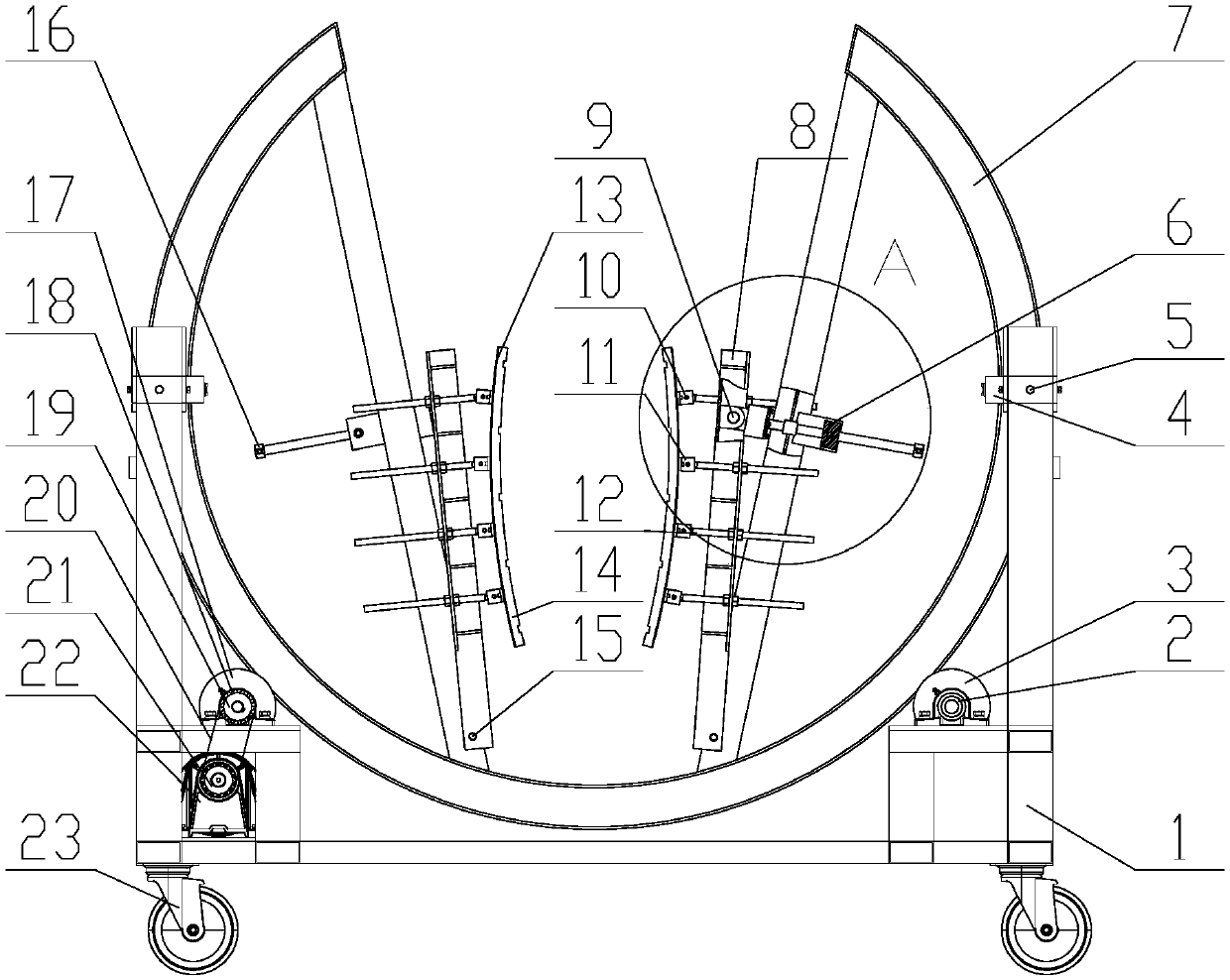
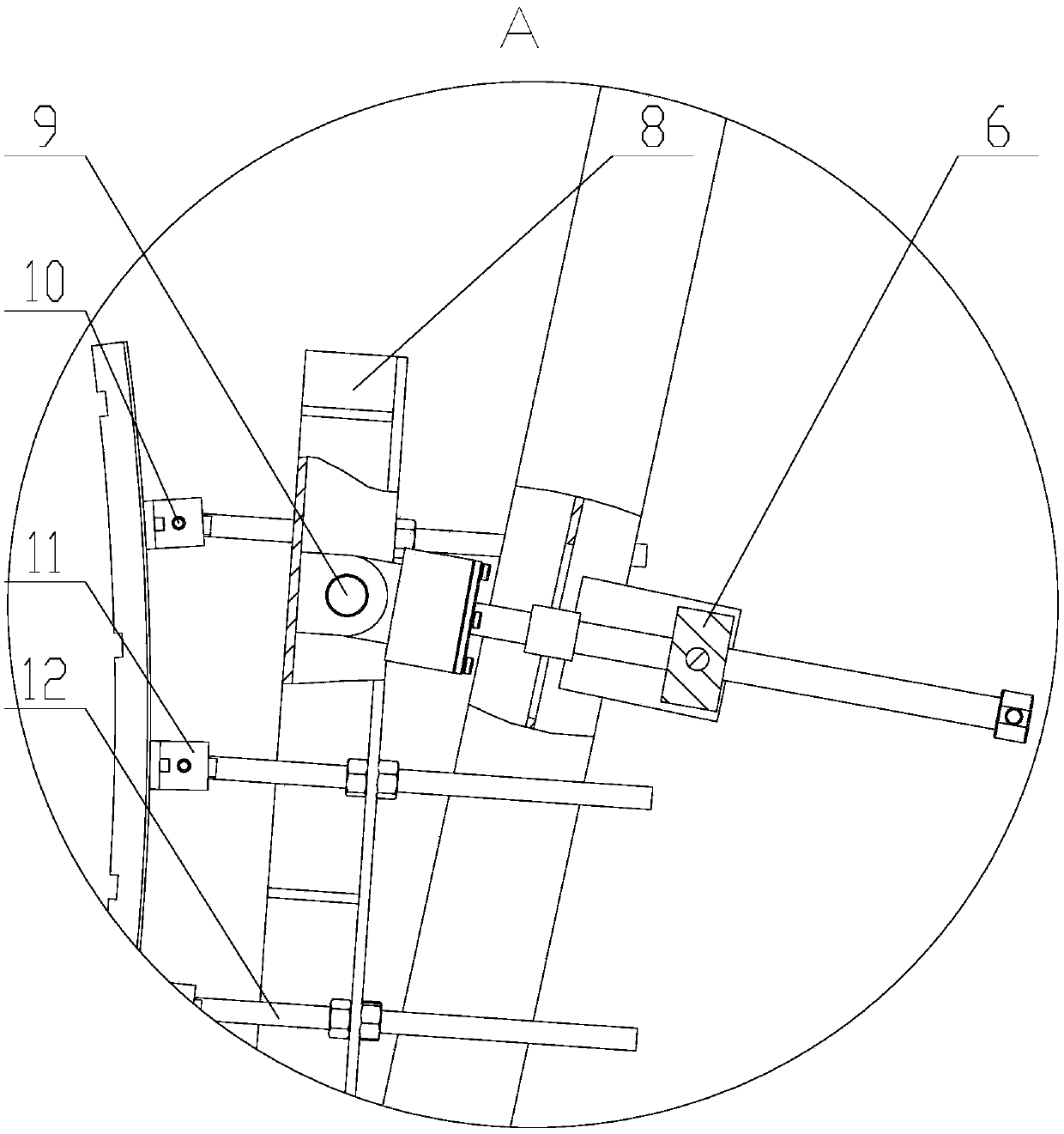
[0035] The invention provides a wind power blade automatic flip clamping device (see Figure 1-11 , hereinafter referred to as the device), the device includes a rotating disk support frame 1, a rotating disk drive mechanism, an annular rotating disk 7, a rotating disk guiding mechanism (including a tensioning structure), a blade fitting clamping mechanism and a control system. The control system controls the action of the rotary disk drive mechanism; the rotary disk drive mechanism is fixed on the rotary disk support frame, the annular rotary disk 7 is in contact with the rotary disk drive mechanism, and is fixed on the rotary disk support frame 1 through the rotary disk guide mechanism, and the blades are attached to each other. The clam...


PUM


Abstract

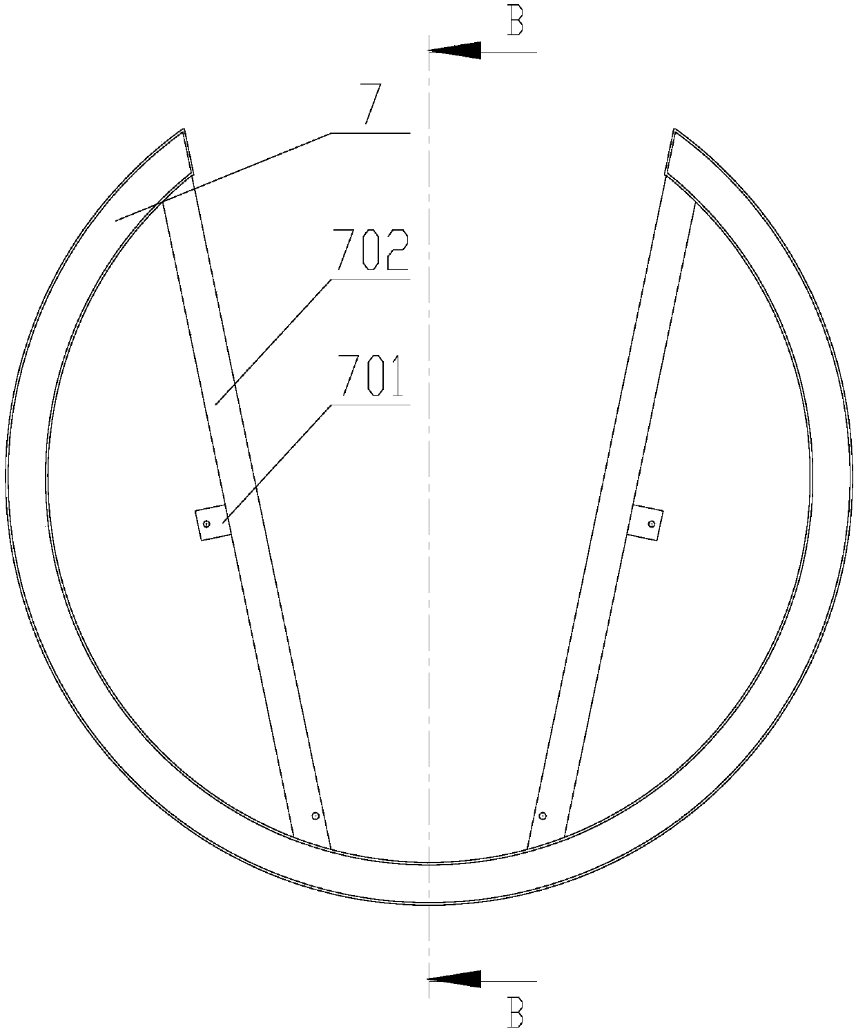
The invention discloses an automatically-overturning clamping device for wind power blades. The device comprises four groups of rotary disc guide mechanisms, wherein annular rotary discs are symmetrically installed on a rotary disc support frame by the four groups of rotary disc guide mechanisms, a notch is formed in the top end of each annular rotary disc, two inclined support beams are welded tothe inner sides of the annular rotary discs at the two sides of each notch, and through holes reserved for the subsequent part installation are formed in the middles of each two support beams; each group of the rotary disc guide mechanisms comprises a guide wheel, a guide wheel shaft, a guide wheel support frame and a tensioning bolt; and each blade bonding clamping mechanism comprises a guide support block, a force-applying screw rod, a screw rod wrench, a thread sleeve, a threaded shaft, a bearing sleeve, a sleeve end cover, a jaw plate, a compression plate, an adjustment screw rod, a support metal plate and a rubber plate. The device is capable of completing support and clamping for the blades by macroscopically adjusting the clamping position of the jaw plate and microcosmically adjusting the bonding posture of the rubber plate, and capable of realizing guide and auxiliary support for the annular rotary discs.

Description

technical field [0001] The invention relates to the field of wind power blade manufacturing, in particular to an automatic turning and clamping device for wind power blades. Background technique [0002] Wind energy is a clean and stable new energy source. With the increasingly serious environmental pollution and greenhouse gas emissions, wind power generation is globally recognized as a solution that can effectively slow down climate change, improve energy security, and promote low-carbon economic growth. Institutions and enterprises are highly concerned. Therefore, wind power has also become one of the fastest growing energy sources in the world in recent years. At present, my country has become the country with the largest and fastest growing wind power generation in the world. [0003] As one of the core components of wind power generation, the manufacture and maintenance of wind turbine blades with complex curved surfaces has always been an industrial problem. Due to...

Claims


Application Information

Patent Timeline
IPC IPC(8): B65G47/90
CPCB65G47/904
Inventor 张慧博张帅戴士杰王小军周润天
Owner HEBEI UNIV OF TECH
Learn More