A Beam Segment Sliding Device Applicable to Curved Beams

A technology of sliding device and beam section, which is applied in bridges, bridge construction, erection/assembly of bridges, etc. It can solve problems such as oil leakage, single applicable working conditions, and difficult control of pulling accuracy

Active Publication Date: 2020-06-02
TONGJI UNIV
View PDF8 Cites 0 Cited by
  • Summary
  • Abstract
  • Description
  • Claims
  • Application Information

AI Technical Summary

Problems solved by technology

This technology can make the position of the beam body have a very high accuracy, but its applicable working conditions are relatively simple, it is only suitable for the construction of straight beam bridges, and it cannot realize the rotation in the sliding plane, which makes the original sliding system used in The precision of curved beam construction is difficult to control
There are mainly the following problems in the traction construction scheme: 1) It is difficult to control the pulling accuracy: theoretically it can be controlled by a computer, but in fact there will be a big accuracy problem when the hoist is pulling
2) The construction equipment is complex: use computer numerical control technology, winches, cables, trolleys or sliding shoes for sliding, there are many equipments, the construction procedures are complicated, and the application and transfer are inconvenient
3) Cannot adapt to the change of beam height: use a trolley or horizontal sliding shoes to slide at the bottom of the beam, and cannot adapt to the change of beam height
[0003] Similarly, the jacking hydraulic sliding construction also has the following problems: 1) The applicable working conditions are single: the sliding shoe and the jack cannot rotate relative to each other, so it is only suitable for straight line bridge construction and cannot be adapted for plane curved beam construction
2) The number of jacks is large and the maintenance cost is high: the current plan uses three-way jacks for construction control, which has problems such as oil leakage and high maintenance costs

Method used


Image

  • A Beam Segment Sliding Device Applicable to Curved Beams
  • A Beam Segment Sliding Device Applicable to Curved Beams
  • A Beam Segment Sliding Device Applicable to Curved Beams

Examples


Embodiment 1

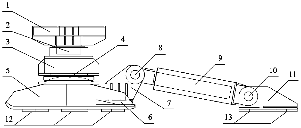
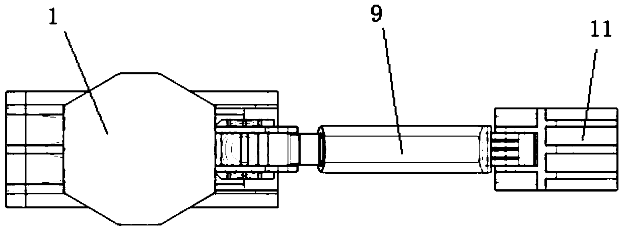
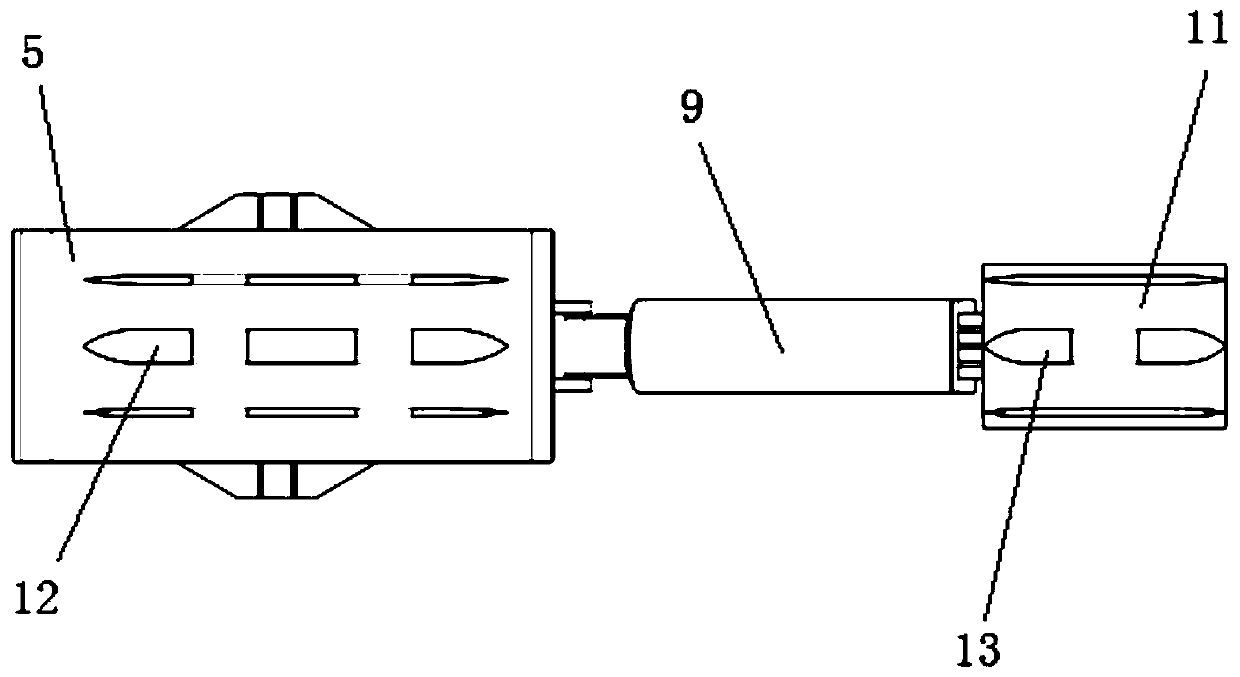
[0035] A beam section sliding device suitable for curved beams, see Figure 1-Figure 6 As shown, it includes the upper bearing platform 1 for supporting the upper bridge segment, the jacking jack 2, the middle support platform 3, the fine-tuning spherical steering wheel 4, the lower sliding shoe 5, the sliding shoe steering wheel 6, the sliding shoe fixing frame 7, Jack front pin shaft 8, promote jack 9, jack tail pin shaft 10, tail slider 11, front slider guide block 12, tail slider guide block 13.

[0036] Among them, the front sliding shoe guide block 12 is welded directly below the lower sliding shoe 5, and the fine-tuning spherical steering wheel 4 is arranged directly above the lower sliding shoe 5; type groove, and buckle on the top of the fine-tuning spherical steering wheel 4, the fine-tuning spherical steering wheel 4 and the middle support platform 3 can cooperate to form a steering structure, which can be adapted to steering in various directions, see Figure 9 an...


PUM


Abstract

The invention relates to a beam segment sliding device suitable for curved beams. The beam segment sliding device comprises an upper bearing platform, a jacking jack, a middle supporting platform anda lower sliding shoe which are successively arranged from top to bottom, the middle supporting platform and the lower sliding shoe are matched through a sphere, and can rotate relatively in the vertical plane, a sliding boot fixing frame capable of rotating in the horizontal plane is further arranged at the rear end of the lower sliding shoe, and the beam segment sliding device further comprises apushing jack and a tail sliding shoe, wherein the sliding boot fixing frame and the tail sliding shoe are rotatably connected to the two ends of the pushing jack correspondingly. Compared with the prior art, according to the beam segment sliding device suitable for the curved beams, through arrangement of two steering regulating mechanisms, the whole beam segment sliding device can be suitable for automatic sliding construction under various working conditions such as the variable beam depth and horizontal curves, and the sliding flexibility and accuracy are improved.

Description

technical field [0001] The invention belongs to the technical field of bridge construction and relates to a beam section sliding device suitable for curved beams. Background technique [0002] Most of the existing curved sliding method construction adopts traction construction, and the sliding trolleys on the inner and outer tracks are respectively pulled by the hoist, and the construction control is carried out by the computer numerical control system. The Zhongxing Bridge uses sliding shoes and three-way jacks to carry out the construction of the sliding assembly method, and uses the hydraulic synchronous sliding system to complete the sliding. The beam section is hoisted to the starting point of sliding, and then slid to the assembly position by the jack. This technology can make the position of the beam body have a very high accuracy, but its applicable working conditions are relatively simple, it is only suitable for the construction of straight beam bridges, and it ca...

Claims


Application Information

Patent Timeline
Patent Type & Authority Patents(China)
IPC IPC(8): E01D21/00E01D21/06
CPCE01D21/00E01D21/06
Inventor 姜旭徐梓齐王傲何振邦许博强杨承志郝晨宇
Owner TONGJI UNIV
Why Eureka
Try Eureka