Differential falling-sill type stilling pool

A differential sill type, stilling pool technology, applied in water conservancy projects, marine engineering, coastline protection and other directions, can solve the problem of the stilling pool energy dissipation rate is not very high, increasing the river bank slope protection project downstream of the stilling pool and so on. , to achieve the effect of shortening the protection range, easy body shape optimization, and strong turbulence

Inactive Publication Date: 2019-04-09
SICHUAN UNIV
View PDF6 Cites 5 Cited by
  • Summary
  • Abstract
  • Description
  • Claims
  • Application Information

AI Technical Summary

Problems solved by technology

However, for a large single-width flow, the energy dissipation rate of the stilling tank is generally not very high, and the water flow out of the tank still contains a large amount of residual energy, causing the water surface fluctuations in the downstream of the river to propagate for a long distance, and the protection works for the river bank slope downstream of the stilling tank are increased.

Method used


Image

  • Differential falling-sill type stilling pool
  • Differential falling-sill type stilling pool
  • Differential falling-sill type stilling pool

Examples


Embodiment 1

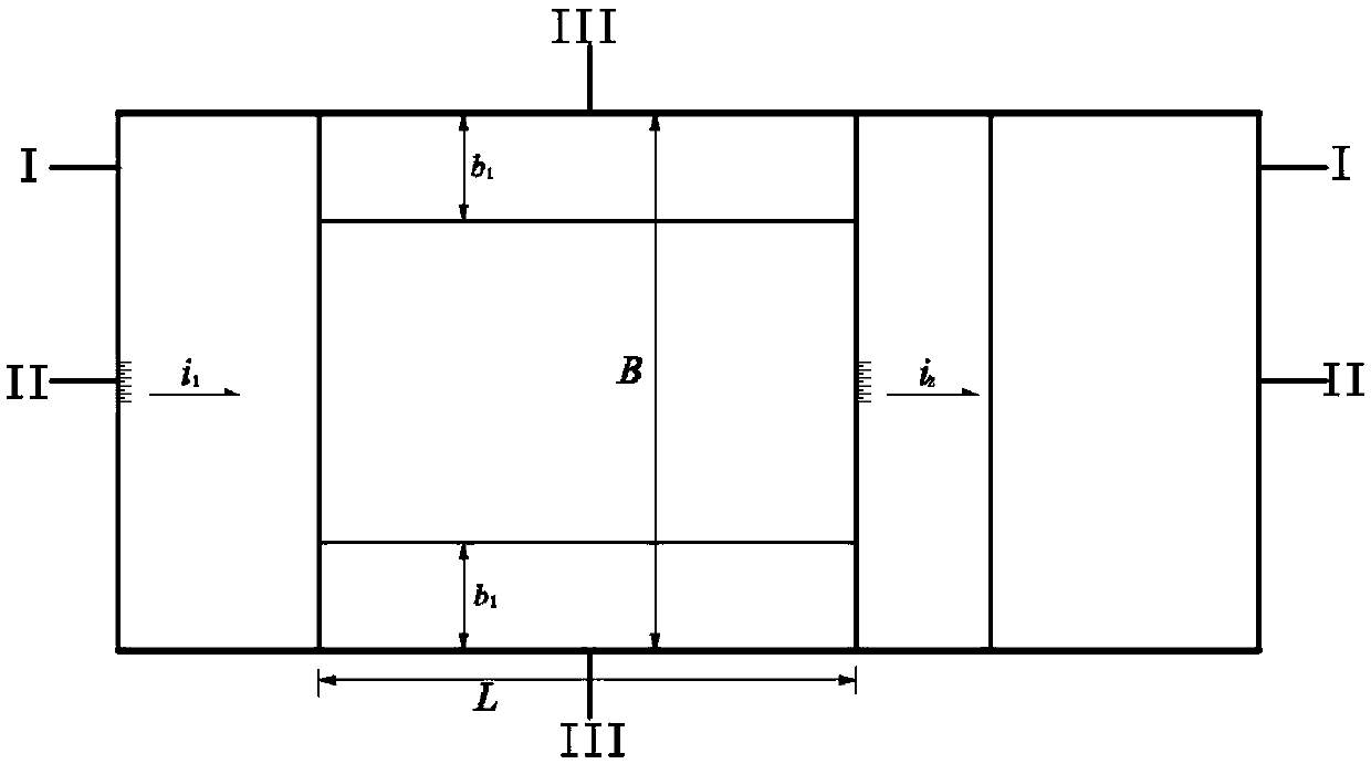
[0035] The A-type differential sill-type stilling pool in this implementation case is used in a middle-head sluice-dam type hydropower station. The stilling pool is composed of a diversion connecting anti-slope section 1, a differential sill stilling pool main section 2, a stilling pool sill anti-slope section 4, which are successively connected in the direction of water flow. The downstream sea is connected, and the inner bottom of the main section 2 of the differential slumping stilling pool is provided with two longitudinal sills 3 along the water flow direction. The two sills are symmetrically attached to the left and right side walls of the stilling pool and are set on the bottom plate of the main section of the stilling pool, and the structural dimensions of the two longitudinal strips are exactly the same.

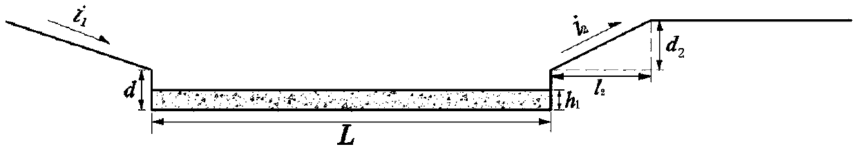
[0036] The water head in front of the gate is 50m, and the maximum single-width flow is q=200m 3 / s.m; the slope of the reverse slope section connected by diversion i ...

Embodiment 2

[0039] In this case, the B-type differential step-down stilling pool is used in a middle-head sluice-dam type hydropower station. It is composed of the reverse slope section 1, the main section of the differential sill stilling pool, and the reverse slope section 4 of the stilling pool tail sill, which are connected in sequence along the flow direction. In connection, the inner bottom of the main section 2 of the differential slumping stilling pool is provided with three longitudinal sills 3 along the water flow direction.

[0040] The water head in front of the gate is 60m and the maximum single-width flow is q=180m 3 / s.m; the slope of the reverse slope section connected by diversion i 1 =d 1 / l 1 =1:8, the horizontal length of the diversion connecting the reverse slope section l 1 =24m, the vertical height d of the anti-slope section connected by the diversion 1 = 3m; the width of the main section of the stilling pool is B=48m, the length is L=55m, and the height of the falling...

Embodiment 3

[0043] The C-type differential falling sill stilling pool in this implementation case is used for the underflow energy dissipation at the spillway exit of the middle water head hydropower station, and the reverse slope section is connected by the diversion in sequence along the flow direction. 1. The differential falling sill stilling pool The main body section 2, the stilling pool sill reverse slope section 4, the stilling pool sill back slope section is connected with the downstream ocean, and the inner bottom of the differential sill stilling pool body section 2 is provided with two longitudinal sections along the water flow direction Article threshold 3.

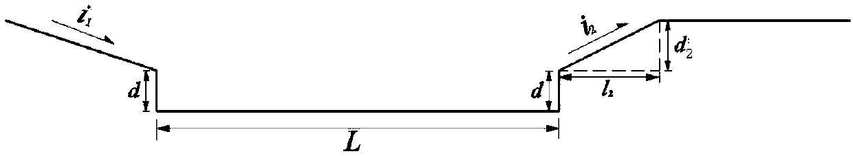
[0044] Among them, the maximum operating head is 80m, the spillway width B=30m, and the maximum single-width flow rate is q=100m 3 / s.m; the slope of the reverse slope section connected by diversion i 1 =d 1 / l 1 =1:6, the horizontal length of the diversion connecting the reverse slope section l 1 =18m, the vertical height d...


PUM


Abstract

The invention aims to provide a differential falling-sill type stilling pool and relates to a novel stilling pool. The differential drop-sill type stilling pool comprises a diversion connection reverse slope section, a differential falling-sill stilling pool main body section and a stilling pool tail sill reverse slope section which are sequentially connected in the water flow direction, wherein the stilling pool tail sill reverse slope section is connected with a downstream apron, and a plurality of longitudinal sills protruding from a bottom plate are arranged on a bottom plate in the differential falling-sill stilling pool main body section in the water flow direction. The differential drop-sill type stilling pool is particularly suitable for underflow energy dissipation of high-speed water flow during flood discharge of hydropower stations, the energy dissipation rate is effectively increased, the hydraulic index near the bottom is reduced, protection engineering of downstream river slope of the stilling pool is reduced and even removed, and thus, construction funds are saved.

Description

Technical field [0001] The invention belongs to a flood discharge and energy dissipation facility used in a water conservancy and hydropower project, and is mainly applied to the underflow energy dissipation of a large single-width flow in a medium-high head hydropower station. Background technique [0002] In water conservancy and hydropower projects, flood discharge and energy dissipation is a very prominent key technical issue. The energy dissipation and erosion prevention downstream of the discharge structure is directly related to the safety of the project. According to a rough statistical analysis of a large amount of actual project data, the cost of flood discharge and energy dissipation accounts for about 40% to 50% of the total project cost, and the cost of energy dissipation and erosion prevention facilities accounts for 40% to 50% of the discharge structure. . Therefore, choosing appropriate flood discharge structures is still an important way to make rational use of ...

Claims


Application Information

Patent Timeline
Patent Type & Authority Applications(China)
IPC IPC(8): E02B8/06
CPCE02B8/06
Inventor 刁明军王磊
Owner SICHUAN UNIV
Why Eureka
Try Eureka