Carbon dioxide driven technical limit spacing optimization method

A carbon dioxide and optimization method technology, which is applied in earthwork drilling, wellbore/well components, production fluid, etc., can solve problems such as large deviations in calculation results, achieve the effects of improving accuracy, increasing economically recoverable reserves, and reducing development costs

Inactive Publication Date: 2019-04-09
北京华成恒业石油技术开发有限公司 +1
View PDF5 Cites 4 Cited by
  • Summary
  • Abstract
  • Description
  • Claims
  • Application Information

AI Technical Summary

Problems solved by technology

[0003] In view of the above situation, in order to overcome the defects of the prior art, the object of the present invention is to provide a method for optimizing the limit well spacing of carbon dioxide flooding technology under different production pressure differences, which effectively solves the problem of calculating the limit well spacing of current CO2 flooding technology with multiple references to water flooding. , the problem of large deviation of calculation results

Method used


Image

  • Carbon dioxide driven technical limit spacing optimization method
  • Carbon dioxide driven technical limit spacing optimization method
  • Carbon dioxide driven technical limit spacing optimization method

Examples


Embodiment 1

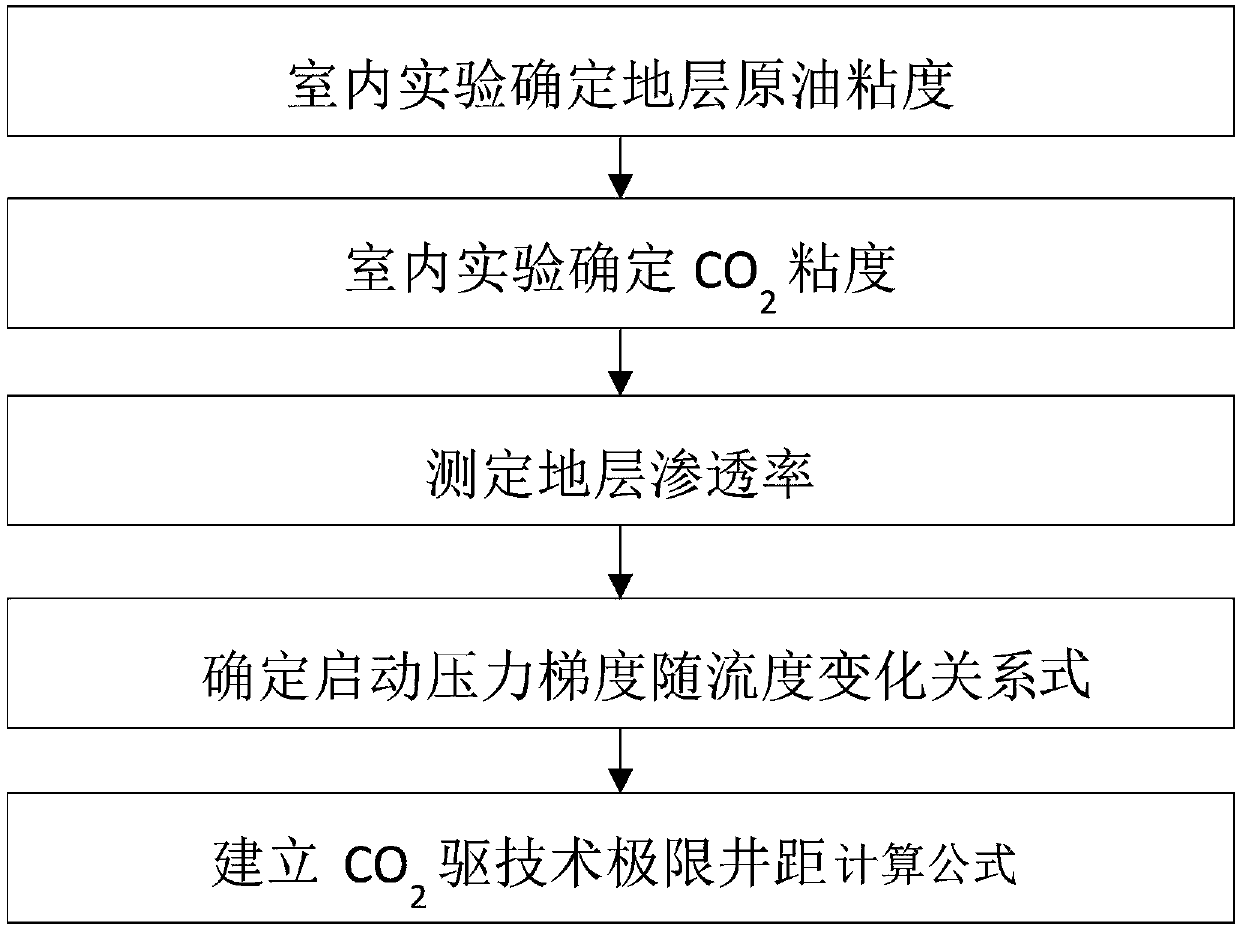
[0030] Embodiment 1, a method for optimizing the limit well spacing of carbon dioxide flooding technology under different production pressure differences, including the following five steps:

[0031] S1. Use the downhole sampler to extract crude oil samples from the L reservoir formation in the wellbore separator of the production well. Using the extracted formation crude oil samples, it is determined through laboratory experiments that the viscosity of the L reservoir formation crude oil is 0.78mPa·s. The specific extraction and determination process can be Obtained by a method for predicting the minimum miscible pressure of CO2 flooding in the patent publication number CN104462753A, which is a prior art and will not be described in detail here;

[0032] S2. Through the formation temperature and pressure test, it is determined that the formation temperature of the L reservoir is 151°C and the formation pressure is 60MPa. The viscosity of CO2 under the formation temperature and...

Embodiment 2

[0043] Embodiment 2. On the basis of Embodiment 1, the step S4 determines that the relationship between the start-up pressure gradient and the flow rate is specifically:

[0044] Through the core displacement experiment, the minimum start-up pressure gradient of CO2 flooding under different permeability cores under bound water, different pressures and different crude oil viscosities was measured, and the change curve of the start-up pressure gradient with the mobility was obtained. The fluidity change relation is:

[0045] G=1 / a·(K / μ) -b

[0046] In the formula: G is the starting pressure gradient, the unit is MPa / m; K is the air permeability, the unit is 10-3μm2; μ is the fluid viscosity, the unit is mPa s; a=3.226, b=0.5992.

Embodiment 3

[0047] Embodiment 3, on the basis of Embodiment 1, the specific steps for establishing the CO2 flooding technology limit well spacing calculation formula in the step S5 are:

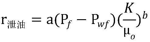
[0048] S51. Using the reservoir engineering method, establish the bottom hole flow pressure of the production well as P wf Time CO 2 Calculation formula of limit oil supply radius of flooding technology;

[0049]

[0050] In the formula: r 泄油 is the oil drainage radius around the production well, in m; P f is formation pressure in MPa; P wf is the bottomhole flow pressure of the production well, in MPa; μ o is the viscosity of formation crude oil, in mPa s;

[0051] S52. Using the reservoir engineering method, establish a formula for calculating the limit displacement radius of the CO2 flooding technology when the bottom hole pressure of the injection well is Pe;

[0052]

[0053] In the formula, r displacement is the displacement radius around the gas injection well, in m; Pf is the formatio...


PUM


Abstract

The invention discloses a carbon dioxide driven technical limit spacing optimization method which comprises the following five steps: S1, carrying out indoor experiment to confirm an in-place oil viscosity; S2, carrying out indoor experiment to confirm a CO2 viscosity; S3, testing in-place permeability; S4, confirming a relation equation that start pressure gradients are changed along with fluidity; S5, establishing a CO2 driven technical limit spacing calculation equation, substituting data of steps S1, S2, S3 and S4 into the equation, and calculating CO2 driven technical limit spacing of anoil reservoir. By adopting the method, on the basis that the situation that the start pressure gradients are changed along with fluidity is confirmed, calculation equations relates to parameters of the CO2 driven technical limit spacing, the in-place permeability, the in-place oil viscosity, the CO2 viscosity under a formation condition, injection-producer pressure differences and the like are established, a calculated CO2 driven technical limit spacing error is within 0-6.0%, the precision of the CO2 driven technical limit spacing is greatly improved, the method can be also applied to low permeability reservoir CO2 driven development schemes in designing well network deployment, and technical guarantee can be provided to achieve beneficial development.

Description

technical field [0001] The invention relates to the technical field of carbon dioxide flooding, in particular to a method for optimizing the limit well spacing of carbon dioxide flooding technology under different production pressure differences. Background technique [0002] At present, the research on reasonable injection-production well spacing in mine fields is mostly based on elastic flooding and water flooding development. There are few reports on the optimization of the limit well spacing of CO2 flooding technology. The oil drainage radius is estimated, and the calculation results have large deviations. Contents of the invention [0003] In view of the above situation, in order to overcome the defects of the prior art, the object of the present invention is to provide a method for optimizing the limit well spacing of carbon dioxide flooding technology under different production pressure differences, which effectively solves the problem of calculating the limit well ...

Claims


Application Information

Patent Timeline
Patent Type & Authority Applications(China)
IPC IPC(8): E21B43/30E21B43/16E21B49/00
CPCE21B43/164E21B43/30E21B49/00
Inventor 聂法健毛洪超丁妍
Owner 北京华成恒业石油技术开发有限公司
Why Eureka
Try Eureka