Buried gas conveying pipeline leakage cross positioning method based on beam forming

A technology for cross positioning and gas transmission pipelines, which is applied in the pipeline system, gas/liquid distribution and storage, mechanical equipment, etc. It can solve the problems of accurate leakage positioning, inability to meet buried pipelines, and inability to achieve accurate three-dimensional positioning. Precise positioning, solving the effect of insufficient precision

Active Publication Date: 2019-04-09
ANHUI UNIV OF SCI & TECH +1
View PDF5 Cites 8 Cited by
  • Summary
  • Abstract
  • Description
  • Claims
  • Application Information

AI Technical Summary

Problems solved by technology

However, this algorithm can only be applied to the precise positioning of close-range sound sources, and it cannot achieve accurate three-dimensional positioning in long-distance scenarios, so it cannot meet the needs of precise positioning of buried pipeline leaks

Method used


Image

  • Buried gas conveying pipeline leakage cross positioning method based on beam forming
  • Buried gas conveying pipeline leakage cross positioning method based on beam forming
  • Buried gas conveying pipeline leakage cross positioning method based on beam forming

Examples


Embodiment 1

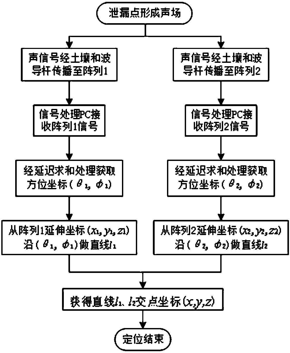
[0067] Based on the above existing technologies and design ideas and principles: see Figure 1-5 : A beamforming-based buried gas pipeline leakage cross-locating method in this embodiment, the method is based on the beamforming method, combined with the principle of cross-location to realize the spatial location of the sound source generated by the buried gas pipeline leakage positioning, thereby completing the positioning of the leakage point, wherein the cross positioning method comprises the following steps:

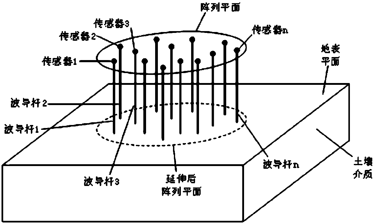
[0068] (1) First place two sensor arrays on the ground above the leaking pipeline and extend into the soil through the waveguide rod; the step (1) is specifically: the two sensor arrays are connected to one end of the waveguide The other ends of the two sets of waveguide rods of the sensor array are inserted into two different positions on the surface above the pipeline, so that the sensor array is still in the air medium, and the waveguide rods can transmit the sound...

Embodiment 2

[0085] The following is a further description of this embodiment with more specific data: a beamforming-based buried gas pipeline leakage cross-locating method in this embodiment uses a beamforming-based double-array cross-locating method for the sound source For the precise location of the leak, after obtaining the area where the sound source of the leak is located, the two sensor arrays, waveguide rods, and signal processing PC required for cross-location are set up in the area.

[0086] Among them, the two sensor arrays are arranged in a cross shape, and each sensor array is composed of 9 acoustic wave sensors, one of which is located at the intersection of the cross shape, and the remaining 8 sensors are evenly arranged on the two intersection lines of the cross shape, and the distance between the sensors is 0.2 m. Each sensor is connected to one end of a waveguide, a total of 18 waveguide rods with the same length. The other end of the waveguide rod is in close contact wi...


PUM


Abstract

The invention discloses a buried gas conveying pipeline leakage cross positioning method based on beam forming. The method is based on a beam forming method, and the space position of a sound source generated at the leakage position of a buried gas conveying pipeline is positioned by combining a cross positioning principle, and then positioning of a leakage point is completed. Compared with the prior art, the cross positioning method has the advantages that two sensor arrays are arranged and are extended to a soil medium through a waveguide rod, a sound source positioning method based on beamforming is improved by means of the cross positioning principle so that three-dimensional positioning of the far-field sound source can be realized through the cross positioning principle, the cross positioning principle is applied to a buried gas conveying pipeline leakage sound wave positioning scene, then accurate positioning of pipeline leakage is realized, and the cross positioning method isa supplement to an existing pipeline leakage detection method based on the sound wave method, and solves the problems that in the prior art, in case of an existing method, the positioning instantaneity is high but the precision is insufficient.

Description

technical field [0001] The invention relates to the technical field of sound source location, in particular to a beamforming-based method for cross-locating leakage of buried gas pipelines. Background technique [0002] In recent years, my country's demand for urban gas has increased year by year, and the total length of gas pipelines has continued to increase, and the hidden dangers of gas leakage have also inevitably increased. Due to the aging and corrosion of pipelines, natural disasters and third-party damage, the accident rate of gas pipelines in my country has reached an average of three times per kilometer per year. Therefore, there is an urgent need to develop a high-precision positioning method for gas pipeline leakage points, real-time monitoring and precise positioning of gas leakage, so that once the gas leakage starts, it will be found and dealt with immediately. [0003] The researchers studied the generation mechanism and propagation characteristics of gas l...

Claims


Application Information

Patent Timeline
Patent Type & Authority Applications(China)
IPC IPC(8): F17D5/06
CPCF17D5/005F17D5/06
Inventor 郑晓亮王强薛生袁宏永付明
Owner ANHUI UNIV OF SCI & TECH
Why Eureka
Try Eureka