
Drying oven used for ceramic product processing

A product, ceramic technology, applied in the field of ceramic product processing ovens, can solve the problems of low convenience, poor mobility, and inability to connect power lines, etc., to achieve the effect of strong convenience and good mobility

Inactive Publication Date: 2019-04-09
HANGZHOU VOCATIONAL & TECHN COLLEGE
View PDF8 Cites 4 Cited by
  • Summary
  • Abstract
  • Description
  • Claims
  • Application Information

AI Technical Summary

Problems solved by technology

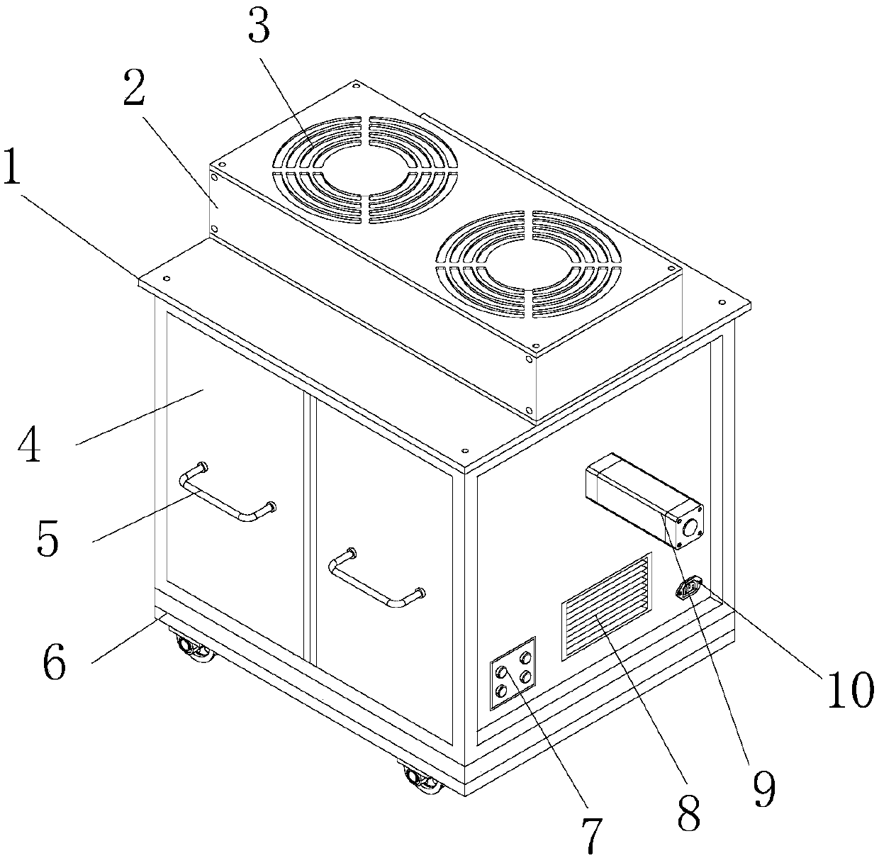
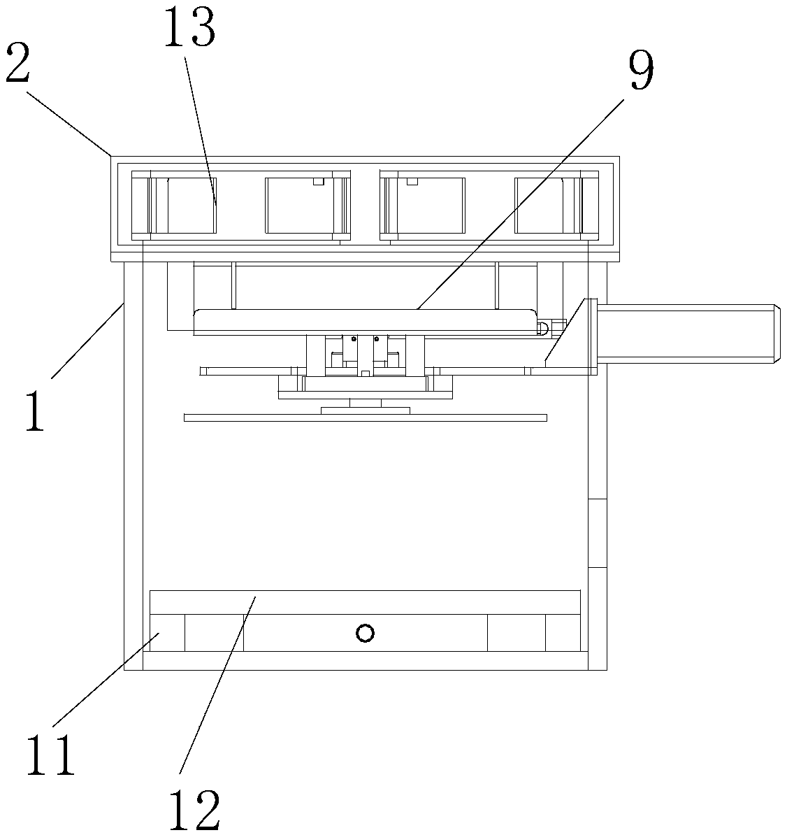
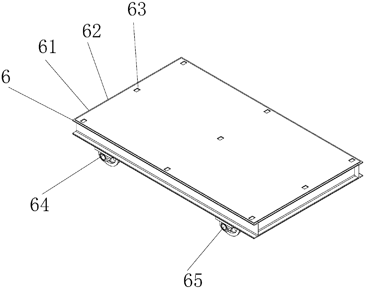
[0009] The present invention provides a ceramic product processing oven through improvement. Before the drying work is finished, the oven needs to be stored and placed in the position where it needs to be placed, and the first motor in the moving device is started to start working. The front end of the first motor The output shaft on the surface starts to rotate, and drives the coupling to make the driving gear move. Since the right side of the driving gear meshes with the driven gear, the driven gear also rotates with it and drives the main shaft to rotate, and the main shaft makes the orientation The wheel rotates, and the power generated by the directional wheel makes the front universal wheel rotate with it. The user uses the hand to control the box to apply force to make the universal wheel move left and right, realize the steering, and complete the electric moving work. During the movement of the box , the power line cannot be connected, and a battery is installed at the left end of the bottom of the machine body, which can provide it with the required electric energy. Problem: During the drying process, ceramic products need to be dried evenly. The controller starts to rotate the electric push rod in the heating device to start working. The output shaft on the left side of the electric push rod drives the rack to move left and right. The rack drives the spur gear at the front end to start rotating during the movement, and the spur gear drives the connecting shaft to start rotating during the movement. The upper end of the connecting shaft passes the bearing to make the connecting disc start to move, and the top of the connecting disc makes the turntable rotate. The heating wire on the turntable achieves uniform rotation to heat the ceramic products. There are fixed blocks at the left and right ends of the connector, and an adjustment rod is installed on the top of the fixed block, which can stably adjust the supporting plate on the top of the adjusting rod. Fix it to prevent the turntable on the support plate from shaking during the rotation, achieve stable rotation, make the heating even, and the effect is good, and solve the problem that the ceramic products cannot be evenly heated during the drying process, and the drying effect is poor problem; when the internal ceramic product is dried, due to the high temperature and poor cooling effect, when the ceramic product needs to be taken out, the control button on the controller starts the second motor to start working, and the front surface of the second motor The output shaft drives the screw to rotate. When the screw rotates, the ball bearing moves back and forth on the screw. The ball bearing drives the slider to make the connecting plate on the top move back and forth, and the connecting plate finally moves the placing plate on the top. , the ceramic products on the top of the placing plate are also pushed out, and the user can take out the dried ceramic products. There are support blocks welded at the four ends of the top of the base, which can support the sliding placing plate to prevent It shakes during the sliding process, so that it can be pushed out stably and has good safety. It solves the problem that the dried ceramic products cannot be automatically pushed out, and the heat of the ceramics after drying is high and the safety is low.

Method used


Image

  • Drying oven used for ceramic product processing
  • Drying oven used for ceramic product processing
  • Drying oven used for ceramic product processing

Examples


Embodiment Construction

[0033] The following will be combined with Figure 1-7 The present invention is described in detail, and the technical solutions in the embodiments of the present invention are clearly and completely described. Apparently, the described embodiments are only some of the embodiments of the present invention, not all of them. Based on the embodiments of the present invention, all other embodiments obtained by persons of ordinary skill in the art without making creative efforts belong to the protection scope of the present invention.

[0034] The present invention provides a ceramic product processing oven through improvement, including a box body 1, an air inlet box 2, an air inlet window 3, an oven door 4, a handle 5, a controller 7, a ventilation window 8, a power interface 10, and a placement plate 12 , blower fan 13, moving device 6, rotating heating device 9 and ejecting device 11, the top middle part of the box body 1 and the four end screw holes in the inner bottom of the ...


PUM

PropertyMeasurementUnit
Thicknessaaaaaaaaaa
Thicknessaaaaaaaaaa
Thicknessaaaaaaaaaa

Abstract

The invention discloses a drying oven used for ceramic product processing. The drying oven used for ceramic product processing comprises a box, a fan, a moving device, a rotary heating device and a pushing-out device. A first motor in the moving device is started to work, an output shaft on the front end face of the first motor starts to rotate and drives a coupling to enable a driving gear to move, a driven gear engaged with the right side of the driving gear also rotates and drives a spindle to rotate, the spindle drives directional wheels to rotate, power generated by the directional wheelsdrives universal wheels at the front ends of the directional wheels to rotate synchronously, users can move the universal wheels leftwards or rightwards by controlling the box by hand to exert force,then steering is achieved, and electric movement is completed. The box cannot be connected with a power line in the moving process, and a storage battery is arranged at the left end of the bottom ofan oven body to supply power demanded, so that the drying oven is convenient to use, good in mobility and capable of being electrically moved, and the problems of poor mobility and inconvenient usingof large equipment are solved.

Description

technical field [0001] The invention relates to the related fields of ceramic processing, in particular to a ceramic product processing oven. Background technique [0002] Ceramics, the Chinese invented pottery as early as about 8000-2000 BC (Neolithic Age). The vessels fired with clay are called pottery, the vessels fired with porcelain clay are called porcelain, and ceramics are pottery, stoneware and porcelain. The general term for ceramics, the ancients called ceramics Ou, and any utensils made of two kinds of clay with different properties, clay and porcelain clay, as raw materials, after ingredients, molding, drying, roasting and other processes can be called ceramics. Nowadays, in the process of ceramics processing All require a drying step, and a dedicated oven is required to dry them efficiently. [0003] However, the existing ceramic product processing oven has the following problems: [0004] 1. The existing ceramic product processing oven has large equipment, p...

Claims


Application Information

Patent Timeline
IPC IPC(8): F26B9/06F26B23/06F26B25/02F26B25/00F26B21/00
CPCF26B9/06F26B21/004F26B23/06F26B25/00F26B25/02F26B2210/02
Inventor 程琼何剑
Owner HANGZHOU VOCATIONAL & TECHN COLLEGE
Learn More