Positioning and punching device for orthopedics department

A punching device and orthopedic technology, applied in the field of medical equipment, can solve problems affecting treatment, punching position deviation, and inability to accurately locate the punching position, achieving good convenience and ensuring accuracy

Inactive Publication Date: 2022-03-01
LUOYANG ORTHOPEDIC TRAUMATOLOGICAL HOSPITAL
View PDF0 Cites 2 Cited by
  • Summary
  • Abstract
  • Description
  • Claims
  • Application Information

AI Technical Summary

Problems solved by technology

[0004] Based on the background technology, there are orthopedic punching devices, which are generally used by medical personnel to punch the affected area by virtue of experience and feeling. In this way, the punching posit

Method used


Image

  • Positioning and punching device for orthopedics department
  • Positioning and punching device for orthopedics department
  • Positioning and punching device for orthopedics department

Examples


Embodiment 1

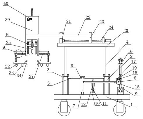
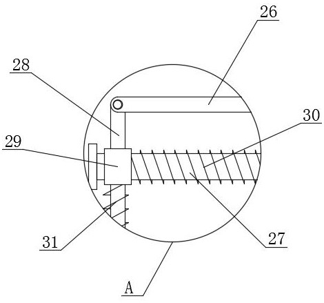
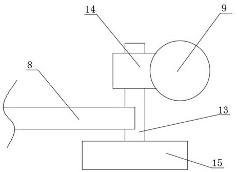
[0037] refer to Figure 1-12In this embodiment, an orthopedic positioning and punching device is proposed, which includes a mobile base 1, a support assembly is connected to the top of the mobile base 1, and a hand lever 9 is connected to the top right side of the mobile base 1, which is set to be able to rotate The hand lever 9 can realize the application of thrust to the mobile base 1, and at the same time, when the drill bit 55 needs to be adjusted in height, it can be conveniently operated. The hand lever 9 is connected with a connecting assembly, and the connecting assembly can make the two support rods 4 It is linked with the hand lever 9, so that the rotational movement of the hand lever 9 can be converted into two support bars 4 for longitudinal movement, and the connecting component is connected with the support component, and the support component is connected with an adjustment component, and the adjustment The assembly is connected with a support beam 22, and the s...

Embodiment 2

[0045] The difference between this embodiment and Embodiment 1 is that: Figure 9 Among them, the transmission assembly includes a moving plate 41, a connection box 42, a driven gear ring 43, a driving gear 45, a transmission rod 46, a scale rod 47 and a driving member. The moving plate 41 is slidably connected to the inner wall of the connection box 42, and the moving Sliding connection between the plate 41 and the connection box 42 can be used to limit the sliding movement of the transmission rod 46, so that only a sliding connection between the transmission rod 46 and the connection box 42 can be carried out, and the mutual connection between the transmission rod 46 and the connection box 42 cannot be realized. Rotate, the scale rod 47 is fixedly installed on the top of the movable plate 41, the displacement of the downward movement of the drill bit 55 can be monitored by setting the scale rod 47, and the depth of the drilled hole can be accurately controlled, and the top of t...


PUM


Abstract

The invention belongs to the technical field of medical instruments, particularly relates to an orthopaedic positioning and punching device, and aims to solve the problems that according to an existing orthopaedic punching device, medical staff generally punch an affected part according to experience and feeling, punching position deviation is easily caused, and later treatment is affected. The top of the movable base is connected with a supporting assembly, the right side of the top of the movable base is rotationally connected with a handrail rod, the handrail rod is connected with a connecting assembly, and the connecting assembly is connected with the supporting assembly. According to the leg perforating device, the legs of a patient can be clamped and positioned while a drill bit is aligned with the positions, needing to be perforated, of the legs of the patient, so that the accuracy can be improved when the legs of the patient are perforated, the perforating depth can be accurately controlled when the legs of the patient are opened, and the perforating efficiency is improved. Therefore, bad influence on later treatment can be avoided.

Description

technical field [0001] The invention relates to the technical field of medical instruments, in particular to an orthopedic positioning and drilling device. Background technique [0002] Orthopedics is one of the most common departments in major hospitals. It mainly studies the anatomy, physiology and pathology of the musculoskeletal system, and uses drugs, surgery and physical methods to maintain and develop the normal form and function of this system. , the spectrum of orthopedic injuries has changed significantly, for example, bone and joint tuberculosis, osteomyelitis, polio and other diseases have decreased significantly, trauma caused by traffic accidents has increased significantly, and the spectrum of orthopedic injuries has changed, which requires orthopedics to keep pace with the times In many fracture treatments, medical staff often need to position and punch the patient's leg bone during the operation; [0003] The orthopedic drilling device in the prior art gene...

Claims


Application Information

Patent Timeline
IPC IPC(8): A61B17/16A61B90/14
CPCA61B17/1626A61B17/16A61B90/14
Inventor 李鹏田慧
Owner LUOYANG ORTHOPEDIC TRAUMATOLOGICAL HOSPITAL
Why Eureka
Try Eureka