
Imaging processing method and device of bistatic synthetic aperture radar SAR system

A technology of synthetic aperture radar and imaging processing, which is applied in measurement devices, radio wave measurement systems, radio wave reflection/reradiation, etc., can solve the problem of high time complexity, low imaging efficiency, and affecting imaging quality and phase preservation of imaging algorithms And other issues

Active Publication Date: 2019-04-09
INST OF ELECTRONICS CHINESE ACAD OF SCI
View PDF5 Cites 11 Cited by
  • Summary
  • Abstract
  • Description
  • Claims
  • Application Information

AI Technical Summary

Problems solved by technology

This is incomparable to the single-base SAR system, because to obtain two or more SAR images of the same area, the single-base SAR system must go through one or more irradiation cycles. The coherence of the image will become weaker, and the accuracy of elevation inversion will decrease
[0004] However, also because the transmitter and receiver are not on the same platform, this creates challenges for bistatic SAR imaging
For bistatic SAR imaging, although the time domain method has good imaging quality, its time complexity is high and the imaging efficiency is low
The derivation of the bistatic SAR spectrum is a key step in the frequency domain method. However, since the slant range history experienced by the transmitter when it irradiates a point target is different from the slant range history experienced by the receiver relative to the point target, when calculating the bistatic SAR Spectrum, the slant distance history is a double square root (Double Square Root, DSR) form, which will make it impossible to use the principle of stationary phase to solve the exact analytical expression of the spectrum
And when deriving the bistatic SAR imaging algorithm, there will inevitably be a large number of formula approximations, which will affect the imaging quality and phase preservation of the imaging algorithm

Method used


Image

  • Imaging processing method and device of bistatic synthetic aperture radar SAR system
  • Imaging processing method and device of bistatic synthetic aperture radar SAR system
  • Imaging processing method and device of bistatic synthetic aperture radar SAR system

Examples


Embodiment Construction

[0143] The present invention will be further described in detail below in conjunction with the accompanying drawings and embodiments.

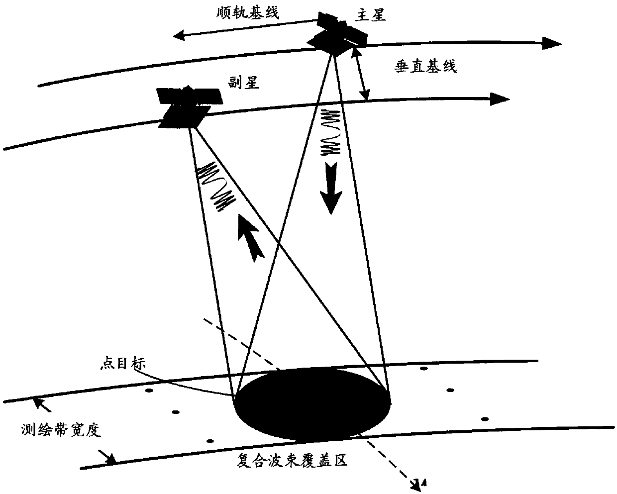
[0144] In order to explain the imaging principle of the bistatic synthetic aperture radar (SAR) system more clearly, figure 1 The geometric diagram of the spaceborne bistatic SAR system is given, in which the primary satellite transmits signals and the secondary satellite receives signals. Obviously, during the entire beam irradiation time, the slant range histories experienced by the main star and the auxiliary star relative to the point target are different, which is the essential difference in imaging between bistatic SAR and monostatic SAR. The algorithm is no longer applicable to bistatic SAR.

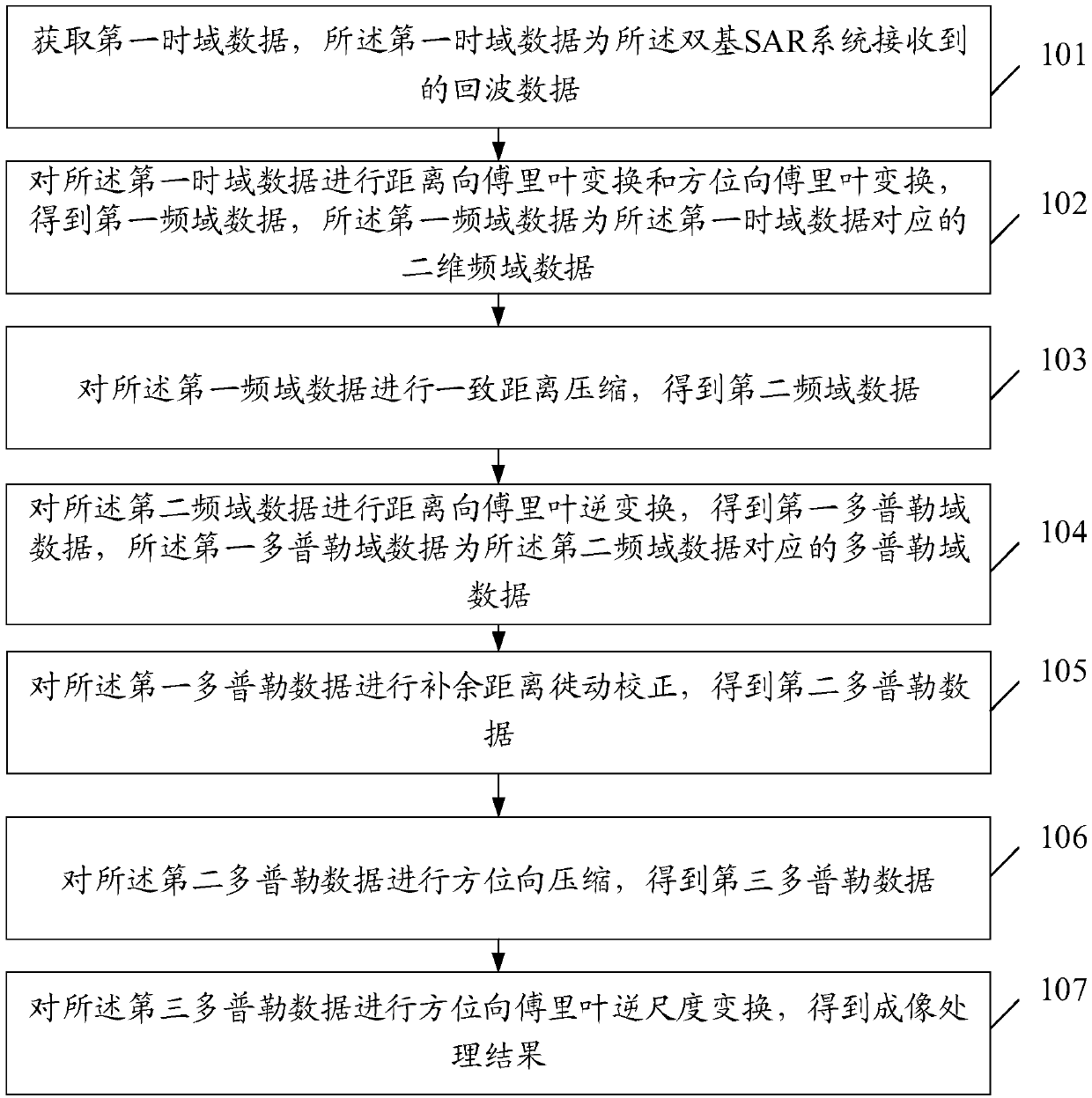
[0145] An embodiment of the present invention provides an imaging processing method for a bistatic SAR system, such as figure 2 shown, including:

[0146] Step 101: Acquire first time domain data, where the first time domain data is echo data ...


PUM


Abstract

The invention discloses an imaging processing method of a bistatic synthetic aperture radar SAR system. The method comprises the steps of: obtaining first time domain data, wherein the first time domain data is echo data received by the bistatic SAR system; carrying out range Fourier transformation and azimuth Fourier transformation on the first time domain data so as to obtain first frequency domain data; carrying out consistent range compression on the first frequency domain data to obtain second frequency domain data; carrying out range inverse Fourier transformation on the second frequencydomain data to obtain first Doppler domain data; carrying out complementary range migration correction on the first Doppler domain data to obtain second Doppler data; carrying out azimuth compressionon the second Doppler data to obtain third Doppler data; and carrying out azimuth inverse Fourier transformation on the third Doppler data to obtain an imaging processing result. The invention furthermore discloses an imaging processing device of the bistatic synthetic aperture radar SAR system.

Description

technical field [0001] The invention relates to the technical field of imaging of a bistatic synthetic aperture radar SAR system, in particular to an imaging processing method, device and computer storage medium of a bistatic SAR system. Background technique [0002] With the development of technology, Synthetic Aperture Radar (SAR) is gradually developing in the direction of high-resolution wide-range and multi-dimensional. High resolution and wide format means that the imaging quality of SAR has higher resolution and larger width; multi-dimensional means that SAR images can contain elevation information and polarization retrieval information of the imaging area. Compared with the traditional single-base SAR, the dual-base / multi-base SAR has obvious advantages in high-resolution wide-field and multi-dimensional imaging. [0003] Since the transmitter and receiver of the bistatic SAR are not on the same platform, the system can generally be divided into two modules, the mai...

Claims


Application Information

Patent Timeline
IPC IPC(8): G01S13/90G01S7/41
CPCG01S7/41
Inventor 李创邓云凯王宇张衡
Owner INST OF ELECTRONICS CHINESE ACAD OF SCI
Learn More