
A high voltage isolation transformer

A high-voltage isolation and transformer technology, applied in the direction of transformers, transformer/inductor parts, transformer/inductor coils/windings/connections, etc., can solve the problems of difficult control of partial discharge, difficult expansion of voltage level, unfavorable winding heat dissipation, etc. Achieve low partial discharge design, reduce the difficulty of insulation design and manufacturing process, and achieve the effect of small volume and structure size

Active Publication Date: 2021-12-21
GLOBAL ENERGY INTERCONNECTION RES INST CO LTD +1
View PDF4 Cites 0 Cited by
  • Summary
  • Abstract
  • Description
  • Claims
  • Application Information

AI Technical Summary

Problems solved by technology

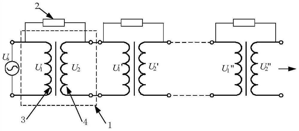
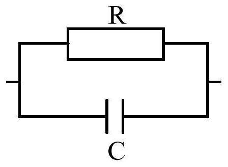
[0006] In order to overcome the problems in the above-mentioned prior art that partial discharge is difficult to control, the voltage level is difficult to expand, and it is not conducive to the heat dissipation of windings, the present invention provides a high-voltage isolation transformer, which includes one or more sub-transformers; when there is one sub-transformer, the high-voltage isolation transformer It is equal to the sub-transformer; when there are multiple sub-transformers, the multiple sub-transformers are connected in cascaded form, and each sub-transformer is connected with a voltage equalizing device in parallel. The high-voltage isolation transformer provided by the invention avoids the situation that partial discharge is difficult to control, and the voltage level Can be extended to hundreds of kilovolts and above, and it is good for winding heat dissipation

Method used


Image

  • A high voltage isolation transformer
  • A high voltage isolation transformer
  • A high voltage isolation transformer

Examples


Embodiment Construction

[0055] The present invention will be described in further detail below in conjunction with the accompanying drawings.

[0056] The high-voltage isolation transformer provided by the embodiment of the present invention is based on a solid insulation structure, adopts a unique structural form and insulation structure, and can realize a dry-type structure design in the voltage range of tens of kilovolts to hundreds of kilovolts, and can realize different voltages at the same time Partial discharge-free design under class. The high-voltage isolation transformer provided by the embodiment of the present invention is formed by cascading several sub-transformers with solid insulation structure. The number of cascading depends on the voltage level of the application. The voltage level of the sub-transformer can be flexible from tens of kilovolts to hundreds of kilovolts. design. Each sub-transformer includes high and low voltage winding structures, iron cores, support structures and ...


PUM


Abstract

The invention provides a high-voltage isolation transformer, which includes one or more sub-transformers; when there is one sub-transformer, the high-voltage isolation transformer is equivalent to the sub-transformer; when there are multiple sub-transformers, the multiple sub-transformers are connected in cascaded form, All transformers are connected in parallel with voltage equalizing devices. The high-voltage isolation transformer provided by the invention avoids the situation that partial discharge is difficult to control. The voltage level can be extended to hundreds of kilovolts and above, and it is beneficial to the heat dissipation of the windings, which can realize effective insulation and isolation in a compact space. Effectively reduce the difficulty of transformer insulation design and manufacturing process and volume; the invention has high insulation withstand strength and low field strength distribution, and at the same time can realize effective suppression of partial discharge, and realize low partial discharge design of transformers, and the voltage level is above 100,000 volts The partial discharge amount does not exceed 50pC; it has the advantages of small structural size, high mechanical strength, and flexible installation.

Description

technical field [0001] The invention relates to the field of high-voltage power transmission, in particular to a high-voltage isolation transformer. Background technique [0002] Power transformers are one of the most commonly used equipment in power systems. They are mainly used for voltage conversion between different voltage levels, power transmission in power systems, and current conversion in systems with different transmission capacities. However, as far as the power transformer itself is concerned, it is a very conventional design. . However, with the current development of power technology, especially the development of flexible AC power transmission and high-voltage direct current power transmission, the functions of power transformers have been expanded, not only limited to power transmission in power systems, but also extended to many other special occasions, such as for some key power Auxiliary power supply of equipment, these occasions require the transformer t...

Claims


Application Information

Patent Timeline
Patent Type & Authority Patents(China)
IPC IPC(8): H01F38/00H01F27/32H01F27/36
CPCH01F27/324H01F27/36H01F38/00H01F2038/006
Inventor 郑健超张升刘远王成昊魏晓光贺之渊孙泽来
Owner GLOBAL ENERGY INTERCONNECTION RES INST CO LTD
Learn More