Supercharge Your Innovation With Domain-Expert AI Agents!

Magnet manufacturing mold

A mold and magnet technology, applied in the field of magnet making molds, can solve the problems of large distortion of magnetic field vector, linear error, inability to meet design requirements, etc., and achieve the effect of reducing distortion and reducing magnetic field strength

Active Publication Date: 2019-04-09
HENGDIAN GRP DMEGC MAGNETICS CO LTD
View PDF7 Cites 0 Cited by
  • Summary
  • Abstract
  • Description
  • Claims
  • Application Information

AI Technical Summary

Problems solved by technology

For other products, it is necessary that the strength of the middle magnetic field is as close as possible to that of the magnetic fields on both sides. If the magnetic field strength in the middle of the magnet manufactured by the above scheme is higher than that of the two sides, the linearity error and the distortion of the magnetic field vector will be large, which cannot meet the design requirements.

Method used


Image

  • Magnet manufacturing mold
  • Magnet manufacturing mold

Examples


Embodiment Construction

[0015] The present invention will be further described below in conjunction with the accompanying drawings and specific embodiments.

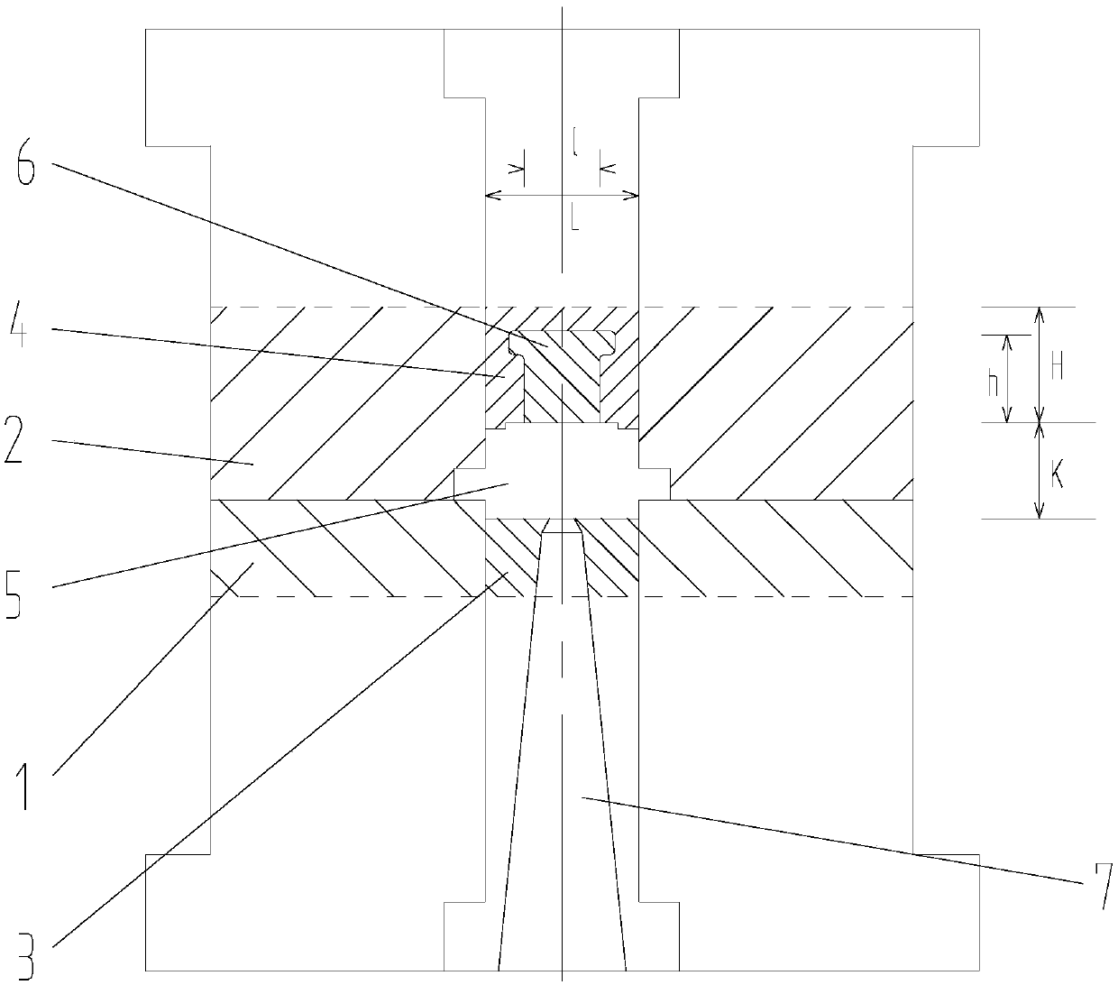
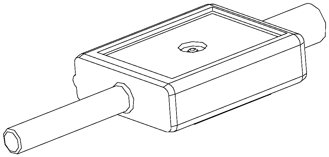
[0016] Such as figure 1 The illustrated embodiment is a mold for making a magnet, which includes a mold A plate 1 and a mold B plate 2 that can be combined up and down, the mold A plate is on the bottom, and the mold B plate is on the top. A mold fitting 3 is installed on the mold A board, and a B mold fitting 4 is installed on the mold B board. The A mold fitting and the B mold fitting are magnetically conductive materials. In this example, 45# steel is used, and the magnetic permeability of the B mold fitting It can be less than the magnetic permeability of A-mode accessories. The A mold fitting and the B mold fitting form a closed concave mold 5 after the mold A plate is fastened with the mold B plate, and the concave mold is used to form a magnet. The final product of the magnet in this example is as follows figure 2 As shown, it is a s...


PUM


Abstract

The invention discloses a magnet manufacturing mold. The magnet manufacturing mold comprises a mold A plate and a mold B plate capable of buckling; an A die accessory is arranged on the mold A plate,and a B die accessory is arranged on the mold B plate; the A die accessory and the B die accessory form a closed concave die, and the magnet is located in the concave die; each of the mold A plate andthe mold B plate is made of non-magnetic-conducting material; the magnetic conductivity of the B die accessory is less than that of the A die accessory. The magnet manufacturing mold disclosed by theinvention has the advantages that the magnetic field intensity in the middle of the magnet can be reduced, and the linear error and the torsion resistance of the magnetic field vector are reduced.

Description

technical field [0001] The invention relates to the technical field of magnet molds, in particular to a magnet manufacturing mold. Background technique [0002] Chinese patent document CN202861398U disclosed on April 10, 2013 "a magnet mold structure that makes the central surface magnetic field higher than the surface magnetic fields on both sides", including an upper mold, a lower mold, a tubular mold and a forming coil, and the forming coil sleeve is placed on the Around the outer surface of the tubular mold; a rectangular upper die is horizontally embedded on the horizontal plane of the lower end of the upper die, and the lower surface of the upper die is movable above the upper port of the tubular die; the upper surface of the lower die is a convex surface , a lower mold equal to the width of the lower mold is fixedly connected to the convex surface of the upper end of the lower mold; the upper mold and the lower mold are made of magnetically conductive materials, and t...

Claims


Application Information

Patent Timeline
IPC IPC(8): H01F41/02
CPCH01F41/02
Inventor 何国栋
Owner HENGDIAN GRP DMEGC MAGNETICS CO LTD
Features
  • R&D
  • Intellectual Property
  • Life Sciences
  • Materials
  • Tech Scout
  • Unparalleled Data Quality
  • Higher Quality Content
  • 60% Fewer Hallucinations
Learn More