
Rotor position monitoring and correcting method and system for permanent magnet synchronous motor, and motor

A permanent magnet synchronous motor and motor rotor technology, applied in the estimation/correction of motor parameters, control system, motor control, etc., can solve problems such as motor runaway, error accumulation, position data error, etc., to prevent feedback errors, avoid The effect of motor runaway and avoiding the danger of motor runaway

Active Publication Date: 2019-04-09
BEIJING INST OF RADIO MEASUREMENT
View PDF6 Cites 1 Cited by
  • Summary
  • Abstract
  • Description
  • Claims
  • Application Information

AI Technical Summary

Problems solved by technology

Since the incremental encoder only has one Z pulse clearing signal per revolution, when encountering problems such as interference during operation, error accumulation and position data errors will occur, which may lead to dangers such as motor runaway

Method used


Image

  • Rotor position monitoring and correcting method and system for permanent magnet synchronous motor, and motor
  • Rotor position monitoring and correcting method and system for permanent magnet synchronous motor, and motor
  • Rotor position monitoring and correcting method and system for permanent magnet synchronous motor, and motor

Examples


Embodiment Construction

[0034] In order to illustrate the present invention more clearly, the present invention will be further described below in conjunction with preferred embodiments and accompanying drawings. Similar parts in the figures are denoted by the same reference numerals. Those skilled in the art should understand that the content specifically described below is illustrative rather than restrictive, and should not limit the protection scope of the present invention.

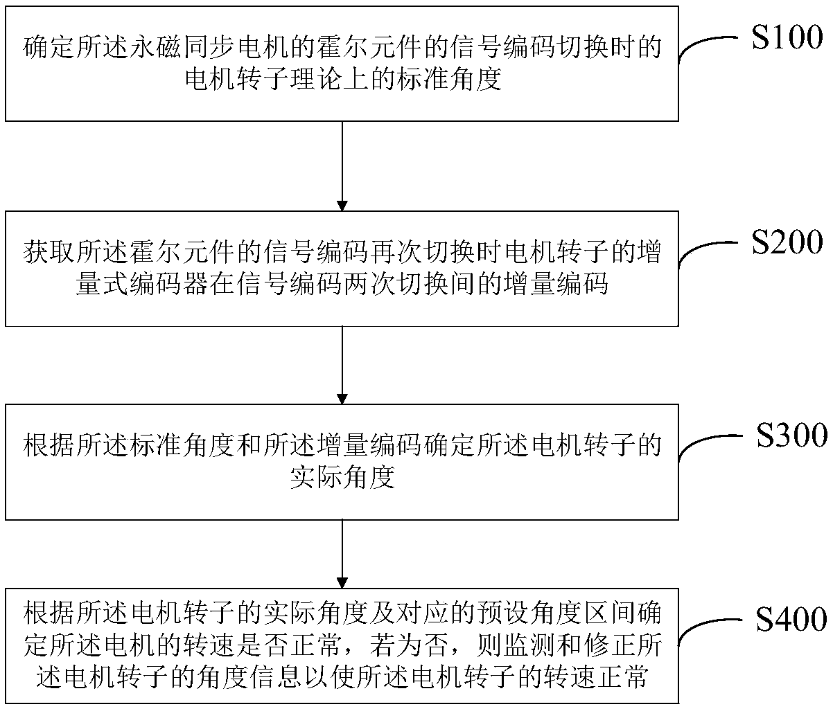
[0035] Such as figure 1 As shown, this embodiment discloses a method for monitoring and correcting the rotor position of a permanent magnet synchronous motor. The method includes:

[0036] S100: Determine a theoretical standard angle of the motor rotor when the signal encoding of the Hall element of the permanent magnet synchronous motor is switched.

[0037] S200: Obtain the incremental code of the incremental encoder of the motor rotor between two signal code switches when the signal code of the Hall element is switched...


PUM


Abstract

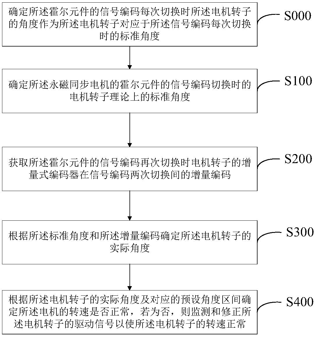
The invention discloses a rotor position monitoring and correcting method and system for a permanent magnet synchronous motor, and the motor. The method comprises the following steps: determining a theoretical standard angle of the motor rotor when a signal coding of a Hall element of the permanent magnet synchronous motor is switched; acquiring an incremental coding of the incremental encoder ofthe motor rotor when the signal coding of the Hall element is switched again, between two switching of signal coding; determining the actual angle of the motor rotor according to the standard angle and the incremental coding; determining whether the rotation speed of the motor is normal according to the actual angle of the motor rotor and the corresponding preset angle interval, and if not, monitoring and correcting the angle information of the motor rotor to make the rotation speed of the motor rotor normal. The invention can detect the signal of the Hall element in real time, and detect andcorrect the incremental position information of the motor rotor according to the Hall signal, thereby effectively avoiding the danger such as the motor being out of control.

Description

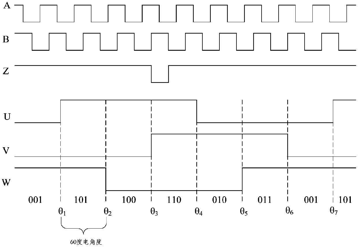
technical field [0001] The invention relates to the technical field of permanent magnet synchronous motors. More specifically, it relates to a permanent magnet synchronous motor rotor position monitoring and correction method, system and motor. Background technique [0002] The permanent magnet synchronous motor is equipped with an incremental encoder and a Hall element that generates U, V, W signals. In the traditional position detection method, the Hall element is only used for the initial position estimation after the motor driver is powered on. During the operation, only the incremental encoder is used to obtain the rotor position. Since the incremental encoder only has one Z pulse clearing signal per revolution, when encountering problems such as interference during operation, error accumulation and position data errors will occur, which may lead to dangers such as motor runaway. Contents of the invention [0003] An object of the present invention is to provide a m...

Claims


Application Information

Patent Timeline
Patent Type & Authority Applications(China)
IPC IPC(8): H02P23/14H02P25/022
CPCH02P23/14H02P25/022H02P2207/05
Inventor 崔永浩
Owner BEIJING INST OF RADIO MEASUREMENT
Learn More