

A mold for stamping and forming of a sleeve and its application method
A stamping forming and sleeve technology, applied in the field of stamping, can solve the problems of cumbersome process flow, low production efficiency, and low material utilization rate, and achieve the effects of reducing impact, improving production efficiency, and improving material utilization rate
- Summary
- Abstract
- Description
- Claims
- Application Information
AI Technical Summary
Problems solved by technology
Method used
Image

Examples
Embodiment Construction
[0025] In order to have a clearer understanding of the technical features, purposes and effects of the present invention, the specific implementation manners of the present invention will now be described with reference to the accompanying drawings. Wherein, the same parts adopt the same reference numerals.
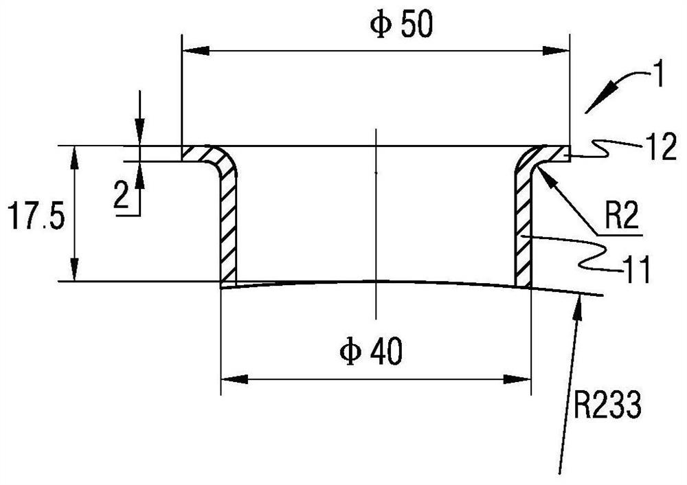
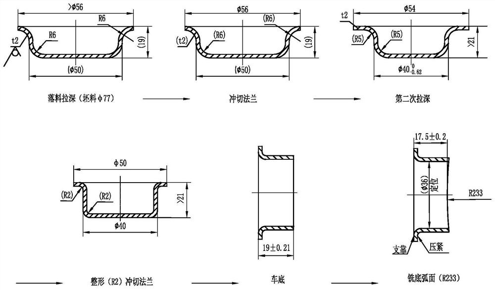
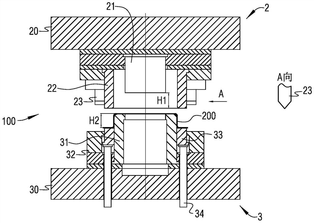
[0026] figure 1 is a schematic cross-sectional structural diagram of an engine sleeve; image 3 It is a schematic cross-sectional structure diagram of a mold for stamping and forming a sleeve according to a specific embodiment of the present invention; image 3 In , the structure of the cutting edge is shown in the partial enlarged schematic diagram of A, Figure 4 for use image 3 Schematic diagram of the process flow of the mold. see figure 1 , image 3 and Figure 4 Shown, the present invention provides a kind of mold that is used for sleeve stamping forming, and it is used for processing such as figure 1 As shown in the sleeve, the wall thickness of the sleeve...
PUM
| Property | Measurement | Unit |
|---|---|---|
| thickness | aaaaa | aaaaa |
| radius | aaaaa | aaaaa |
| radius | aaaaa | aaaaa |
Abstract
Description
Claims
Application Information