Cutting device for aluminum bar

A cutting device and aluminum rod technology, which is applied in the field of aluminum processing, can solve the problems of uninterrupted cutting work and reduce work efficiency, and achieve the effects of improving cutting efficiency, saving labor, and improving work efficiency

Active Publication Date: 2019-04-12
台州市金美铝业股份有限公司
View PDF6 Cites 2 Cited by
  • Summary
  • Abstract
  • Description
  • Claims
  • Application Information

AI Technical Summary

Problems solved by technology

However, after the above-mentioned device cuts one end of the aluminum rod, it needs to wait for the bridge frame and the aluminum rod clamping parts to be reset before cutting the next section of the aluminum rod, which cannot achieve continuous and uninterrupted cutting work, which reduces the work efficiency and needs to be improved.

Method used


Image

  • Cutting device for aluminum bar
  • Cutting device for aluminum bar
  • Cutting device for aluminum bar

Examples


Embodiment Construction

[0038] The present invention will be described in further detail below in conjunction with the accompanying drawings.

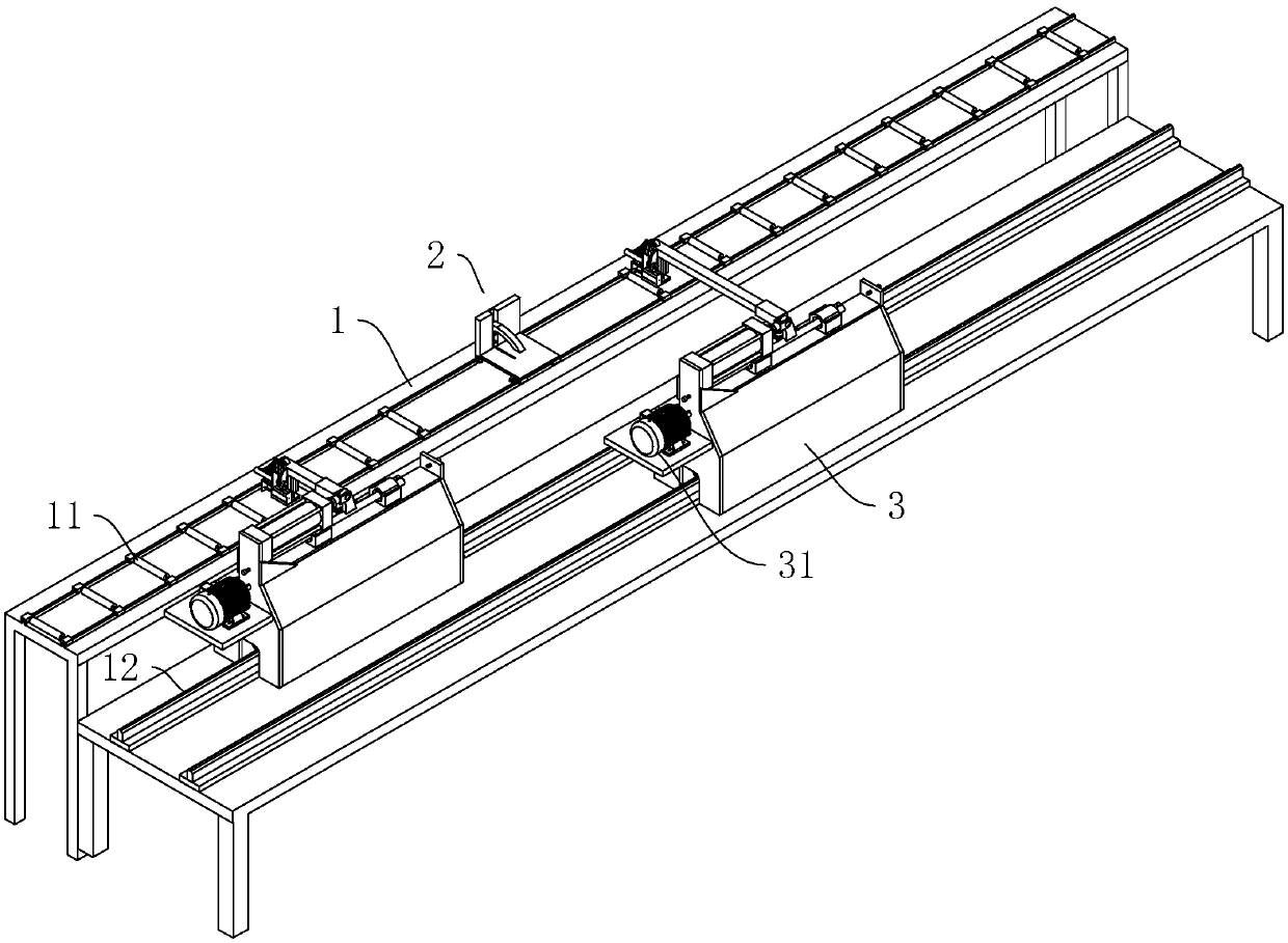
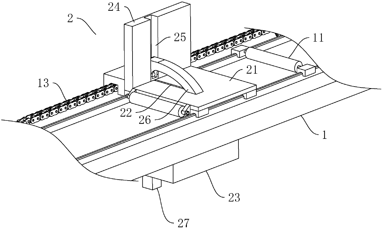
[0039] Such as figure 1 , figure 2 As shown, a cutting device for aluminum rods includes a horizontally arranged transmission frame 1, a number of transmission rollers 11 rotatably connected to the transmission frame 1, and the transmission rollers 11 are evenly arranged along the length direction of the transmission frame 1. A cutting mechanism 2 is provided in the middle of the transmission frame 1 . The cutting mechanism 2 includes a base 21 through which a strip-shaped cutting hole 22 is penetrated. A cutting saw 23 located below the cutting hole 22 is provided on the lower surface of the base 21 .

[0040] Such as figure 2 As shown, a limiting seat 24 is vertically provided on the side of the base 21 away from the support frame 3 , and a limiting groove 25 is vertically provided on the inner side wall of the limiting seat 24 . The limit groove 25 i...


PUM


Abstract

The invention discloses a cutting device for an aluminum bar, and relates to the technical field of machining of aluminum materials. The device comprises a conveying frame, a cutting mechanism is arranged in the middle of the conveying frame, a pair of sliding rails is arranged on one side of the conveying frame side by side, supporting frames are connected to the sliding rails in a sliding mode,walking motors are arranged on the side walls of the supporting frames, sliding rods are connected to the upper end faces of the supporting frames in a sliding mode, first air cylinders drive the sliding rods to slide, racks are arranged on the side walls of the sliding rods, rotating shafts are rotationally connected to the supporting frames, gears meshed with the racks are arranged on the outerwalls of the rotating shafts, cantilevers are horizontally arranged on the rotating shafts, clamping mechanisms used for clamping the aluminum bar are arranged on the cantilevers, and the lower end surface of the cantilever located on the outer side is higher than the upper end surface of the other cantilever. The cutting device for the aluminum bar has the advantages and effects that the aluminumbar can be conveyed through the supporting frames which are arranged in a staggered mode, so that it is guaranteed that the aluminum bar is always in a conveyed state, continuous and uninterrupted cutting work of the aluminum bar can be achieved, the cutting speed of the aluminum bar is increased, and the effect of high working efficiency is achieved.

Description

technical field [0001] The invention relates to the technical field of processing aluminum materials, in particular to a cutting device for aluminum rods. Background technique [0002] Aluminum and its alloys have a series of excellent properties. In the application of metal materials, the application of aluminum is second only to the application of steel, ranking second. Among them, the aluminum rod is the raw material for producing aluminum profiles. When producing aluminum profiles, the aluminum rods need to be cut into sections of cylinders for later use. [0003] Chinese patent CN105290500B discloses a cutting device for aluminum rods, which includes feeding rails, discharging rails, cutting saw wheels and rollers, and also includes moving components, aluminum rod fixing components and a digital control platform. The moving components include drive motors, The roller, the connecting plate and the bridge frame that roll and connect the roller and the feeding track toget...

Claims


Application Information

Patent Timeline
Patent Type & Authority Applications(China)
IPC IPC(8): B23D19/00B23D33/02B23Q7/00
CPCB23D19/00B23D33/02B23Q7/00
Inventor 黄高勇张伟
Owner 台州市金美铝业股份有限公司
Why Eureka
Try Eureka