Modular DC Transformer Based on Discrete Switched Capacitor and Its Modulation Method
A technology of DC transformers and switched capacitors is applied in the direction of converting DC power input to DC power output, adjusting electrical variables, instruments, etc., which can solve the problem of increasing the operating loss and cost of DC power grids, difficult to realize online input of redundant modules, and difficult to realize modulation. and control flexibility, to achieve the effect of non-stop cutting, flexible modulation and control strategy, and reduce manufacturing and design costs
- Summary
- Abstract
- Description
- Claims
- Application Information
AI Technical Summary
Problems solved by technology
Method used
Image
Examples
Embodiment 1
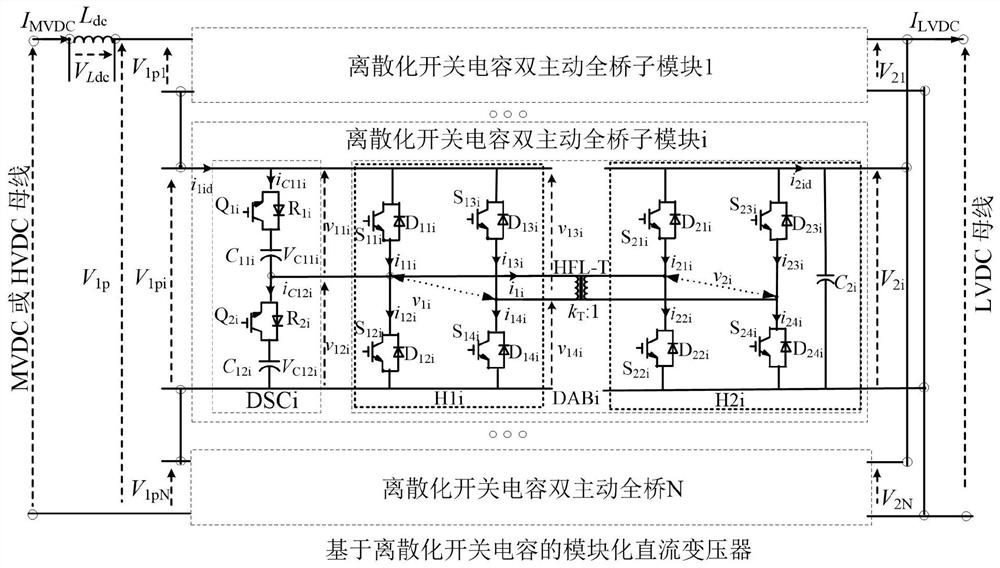
[0041] Example 1, such as figure 1 As shown, the discrete switched capacitor dual-active full-bridge sub-module DSC-DABi under this embodiment includes a discrete switched capacitor module DSCi and a dual-active full-bridge sub-module DABi; the discrete switched capacitor dual-active full-bridge sub-module DSC -DABi is connected in series to the medium (high) voltage DC bus through the discrete switched capacitor module DSCi, and the discrete switched capacitor dual-active full-bridge sub-module DSC-DABi is connected to the first connection terminal on the low-voltage DC side of the dual-active full-bridge sub-module DABi. The second link terminal on the low-voltage DC side is connected in parallel to the low-voltage DC bus; on the medium (high) voltage DC side, multiple discrete switched capacitor dual-active full-bridge sub-modules DSC-DAB are used in series to improve the withstand voltage level of the DC transformer. The low-voltage interface side adopts a parallel structu...
Embodiment 2
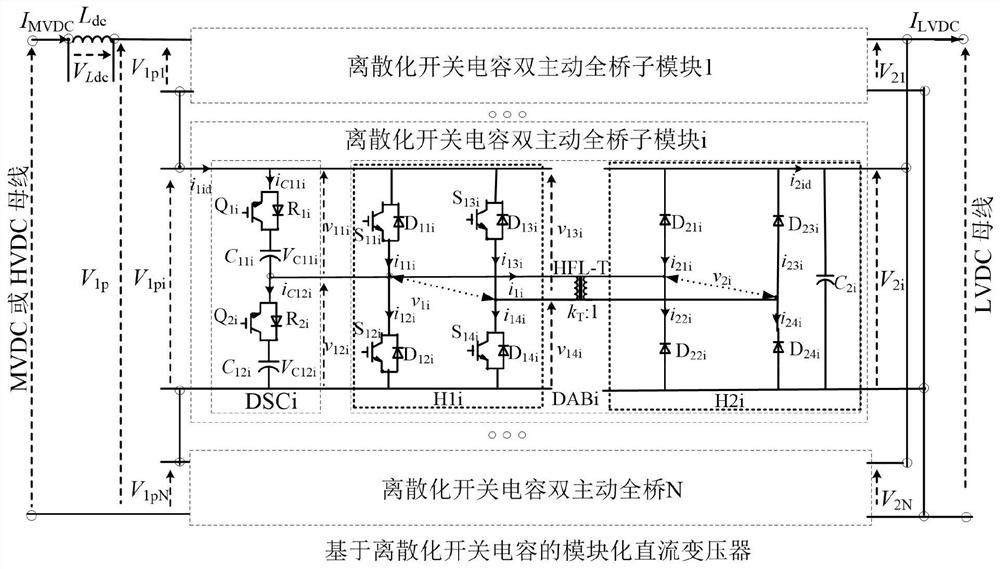
[0046] Embodiment 2, as another embodiment of the present invention, such as figure 2 As shown, the difference from Embodiment 1 is only that the switching tube of the output circuit H2i of the dual-active full-bridge sub-module DABi is removed, specifically:
[0047] The first leg of the output circuit H2i includes a diode D 21i composed of the first high-side arm, and the diode D 22i composed of the first lower bridge arm; the second bridge arm of the output circuit H2i includes a diode D 23i composed of the second upper arm, and the diode D 24i Composed of the second lower bridge arm, the diode D 23i The negative parallel switch capacitor C 2i , Diode D 24i The positive parallel switch capacitor C 2i , switched capacitor C 2i The positive pole of the discretized switch capacitor is connected to the first connection terminal of the dual active full-bridge sub-module DSC-DABi, and the switch capacitor C 2i The negative pole of the discrete switching capacitor is conn...
Embodiment 3
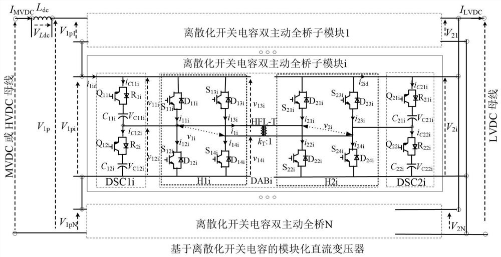
[0048] Embodiment 3, as another kind of embodiment of the present invention, such as image 3 As shown, the difference from Embodiment 1 is only that the switched capacitor C is replaced by the discrete switched capacitor module DSC 2i ; Cause the dual active full-bridge submodule DSC-DABi of the discrete switched capacitor to include two discrete switched capacitor modules DSCi (discrete switched capacitor module DSC1i, discrete switched capacitor module DSC 2i ) and a dual-active full-bridge sub-module DABi; the discrete switched-capacitor dual-active full-bridge sub-module DSC-DABi is connected in series to the medium (high) voltage DC bus through the discrete switched-capacitor module DSC1i, and the discrete switched-capacitor dual-active full-bridge The sub-module DSC-DABi passes through the discretized switched capacitor module DSC 2i The first connection terminal on the low-voltage DC side and the second connection terminal on the low-voltage DC side are connected in p...
PUM
 Abstract
Description
Claims
Application Information
 - R&D
- Intellectual Property
- Life Sciences
- Materials
- Tech Scout
- Unparalleled Data Quality
- Higher Quality Content
- 60% Fewer Hallucinations
Browse by: Latest US Patents, China's latest patents, Technical Efficacy Thesaurus, Application Domain, Technology Topic, Popular Technical Reports.
© 2025 PatSnap. All rights reserved.Legal|Privacy policy|Modern Slavery Act Transparency Statement|Sitemap|About US| Contact US: help@patsnap.com


