
Circuit board laser cutting equipment and application method

A laser cutting and circuit board technology, which is applied in laser welding equipment, welding equipment, metal processing equipment, etc., can solve the problems of short service life of ultraviolet lasers and green lasers, low efficiency of mechanical splitting, and middle cutting efficiency, etc., and achieve effective Conducive to transshipment, improve processing efficiency, and precise processing accuracy

Pending Publication Date: 2019-04-12
天津镭恒自动化科技有限公司
View PDF0 Cites 1 Cited by
  • Summary
  • Abstract
  • Description
  • Claims
  • Application Information

AI Technical Summary

Problems solved by technology

[0002] When cutting circuit boards, the existing technologies include mechanical splitting, ultraviolet laser and green laser cutting. These three common cutting methods have their own advantages and disadvantages. The efficiency of mechanical splitting is low, and the edges after splitting need to be polished. There are many processes, and the edge effect of ultraviolet laser cutting is better, but the efficiency is low; the efficiency of green laser cutting is in the middle, and the cutting effect is slightly worse; and the life of ultraviolet laser and green laser is short, the maintenance cost is high, and the theoretical life is 15000-20000 hours. Regular maintenance and replacement are required, and the maintenance cost is relatively high

Method used


Image

  • Circuit board laser cutting equipment and application method
  • Circuit board laser cutting equipment and application method
  • Circuit board laser cutting equipment and application method

Examples


Embodiment Construction

[0036] It should be noted that, in the case of no conflict, the embodiments of the present invention and the features in the embodiments can be combined with each other.

[0037] In describing the present invention, it should be understood that the terms "center", "longitudinal", "transverse", "upper", "lower", "front", "rear", "left", "right", " The orientations or positional relationships indicated by "vertical", "horizontal", "top", "bottom", "inner" and "outer" are based on the orientations or positional relationships shown in the drawings, and are only for the convenience of describing the present invention and Simplified descriptions, rather than indicating or implying that the device or element referred to must have a particular orientation, be constructed and operate in a particular orientation, and thus should not be construed as limiting the invention. In addition, the terms "first", "second", etc. are used for descriptive purposes only, and should not be understood ...


PUM


Abstract

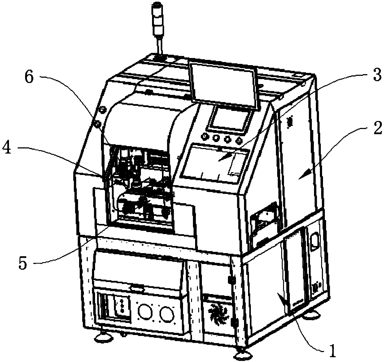
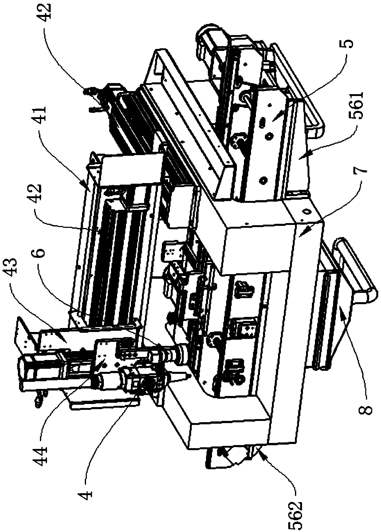
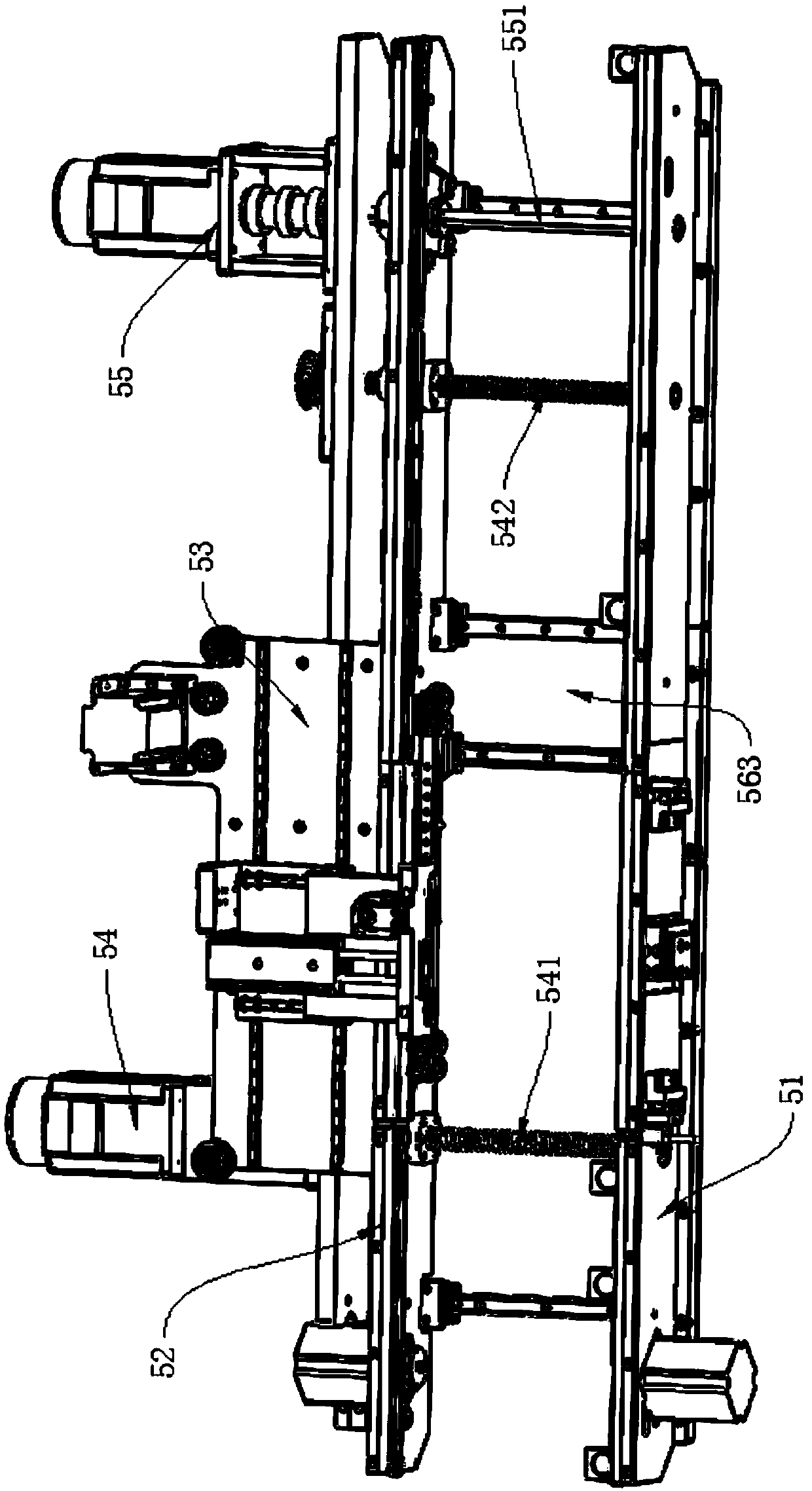
The invention provides circuit board laser cutting equipment and an application method thereof and belongs to the field of laser cutting equipment. The equipment comprises a workbench, a conveying assembly and a laser cutting gun. The laser cutting gun is arranged on the workbench and reciprocates relative to the workbench in the directions of the X-axis, Y-axis and the Z-axis. The conveying assembly is arranged above the workbench and arranged along the X axis. The conveying assembly comprises a front plate group and a rear plate group which are same in structure and arranged symmetrically. The front plate group and the rear plate group are arranged in parallel along the X axis. A first conveying belt arranged symmetrically and a second conveying belt arranged symmetrically are arranged on the inner sides of the front plate group and the rear plate group correspondingly. A push manipulator used for achieving circuit board transfer is arranged between the first conveying belt and the second conveying belt, arranged on the side, away from the front plate group, of the rear plate group and located in the middle of the workbench. The circuit board laser cutting equipment is high in cutting precision, high in efficiency, stable in performance, long in service life and low in subsequent maintenance cost.

Description

technical field [0001] The invention belongs to the field of laser cutting equipment, and relates to circuit board laser cutting equipment and a use method. Background technique [0002] When cutting circuit boards, the existing technologies include mechanical splitting, ultraviolet laser and green laser cutting. These three common cutting methods have their own advantages and disadvantages. The efficiency of mechanical splitting is low, and the edges after splitting need to be polished. There are many processes, and the edge effect of ultraviolet laser cutting is better, but the efficiency is low; the efficiency of green laser cutting is in the middle, and the cutting effect is slightly worse; and the life of ultraviolet laser and green laser is short, the maintenance cost is high, and the theoretical life is 15000-20000 hours. Regular maintenance and replacement are required, and the maintenance cost is relatively high. Contents of the invention [0003] The problem to ...

Claims


Application Information

Patent Timeline
Patent Type & Authority Applications(China)
IPC IPC(8): B23K26/38B23K26/08B23K26/70B23K101/42
CPCB23K26/0884B23K26/38B23K26/702
Inventor 李树勇田红伟
Owner 天津镭恒自动化科技有限公司
Learn More