

Method for locking and pressing false boss
A process boss and stop technology, which is applied in the direction of manufacturing tools, metal processing equipment, metal processing machinery parts, etc., can solve the problems of increased process and cost, process boss rotation, and insufficient pressing force, so as to reduce displacement and The effect of rotating amount, preventing crushing and easy installation
- Summary
- Abstract
- Description
- Claims
- Application Information
AI Technical Summary
Problems solved by technology
Method used
Image

Examples
Embodiment 1
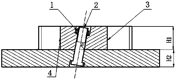
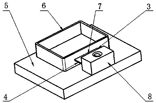
[0030] The present invention is realized through the following technical solutions, as Figure 1-Figure 3 As shown, a method for stopping and compressing the process boss 8 is to select the compression screw according to the position and size of the process boss 8 of the part 6, and to process one on the process boss 8 and the tooling 5 to form a plane with the tooling 5. Stepped through holes with an included angle α, the small ends of the two stepped through holes are connected to form a compression screw hole for installing a compression screw; install and tighten the tightening screw in the compression screw hole, so that the tooling 5 and the part 6 are close .
[0031] It should be noted that, through the above improvements, fixing the process boss 8 of the part 6 by using the pressing screw with an inclination angle can increase the radius of action of the pressing force, increase the moment under the same pressing force, and help reduce the process boss 8 The amount o...
Embodiment 2
[0034] This embodiment is further optimized on the basis of the above-mentioned embodiments such as figure 1 As shown, further, in order to better realize the present invention, the following steps are specifically included:
[0035] Step S1: According to the structural characteristics of the process boss 8 and the tooling 5, and the positions of the cut-in end 4 and the cut-out end 3 when the process boss 8 is removed, determine the screw inclination direction, set the screw inclination angle α, and calculate the corresponding screw length L;
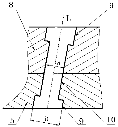
[0036] Step S2: Determine the axis in the longitudinal direction of the compression screw hole according to the bottom plane profile of the process boss 8 and the screw inclination angle; the axis in the longitudinal direction is parallel to the side of the tooling 5 .
[0037] Step S3: Select an appropriate screw diameter specification according to the width of the process boss 8 and the processing stability requirements, and determi...
Embodiment 3
[0043] This embodiment is further optimized on the basis of the above embodiments, such as figure 1 As shown, further, in order to better realize the present invention, the direction of inclination of the screw is that the side of the screw away from the tooling 5 is inclined toward the cutting end 3, and the inclination angle α<90°.
[0044] Further, in order to better realize the present invention, the length of the tooling 5 along the axial direction of the longitudinal direction of the compression screw is H2, and the length of the process boss 8 along the axial direction of the longitudinal direction of the compression screw is H1; The length of the screw rod 2 in the screw is L, and said L
[0045] It should be noted that, through the above improvement, the adoption of the above method even effectively ensures that the length of the screw is always thinner than the thickness of the process boss 8 and the thickness of the tooling 5 . Effectively prevent the s...
PUM
| Property | Measurement | Unit |
|---|---|---|
| Thickness | aaaaa | aaaaa |
| Length | aaaaa | aaaaa |
Abstract
Description
Claims
Application Information