Sludge negative-pressure ceramic membrane concentration integrated machine

A technology of ceramic membrane and integrated machine, which is applied in sludge treatment, water/sludge/sewage treatment, chemical instruments and methods, etc., can solve the problems of large footprint, low concentration efficiency, unstable concentration, etc. Less land area, high concentration efficiency, and low operating cost

Pending Publication Date: 2019-04-12
曾从根
View PDF8 Cites 0 Cited by
  • Summary
  • Abstract
  • Description
  • Claims
  • Application Information

AI Technical Summary

Problems solved by technology

[0002] At present, ordinary sludge concentration in the market is generally used as a concentration tank for gravity concentration. The construction cost of the concentration tank is large, the floor area is large, the sludge concentration time is long, and the efficiency is low. It is not suitable for large-scale sludge treatment plants.
Some also use screw stackers for sludge concentration, but they need to add chemicals, the concentration efficiency is low, the concentration of sludge is unstable after concentration, and the SS content in the filtrate is high, so it cannot be discharged directly

Method used


Image

  • Sludge negative-pressure ceramic membrane concentration integrated machine
  • Sludge negative-pressure ceramic membrane concentration integrated machine
  • Sludge negative-pressure ceramic membrane concentration integrated machine

Examples


Embodiment 1

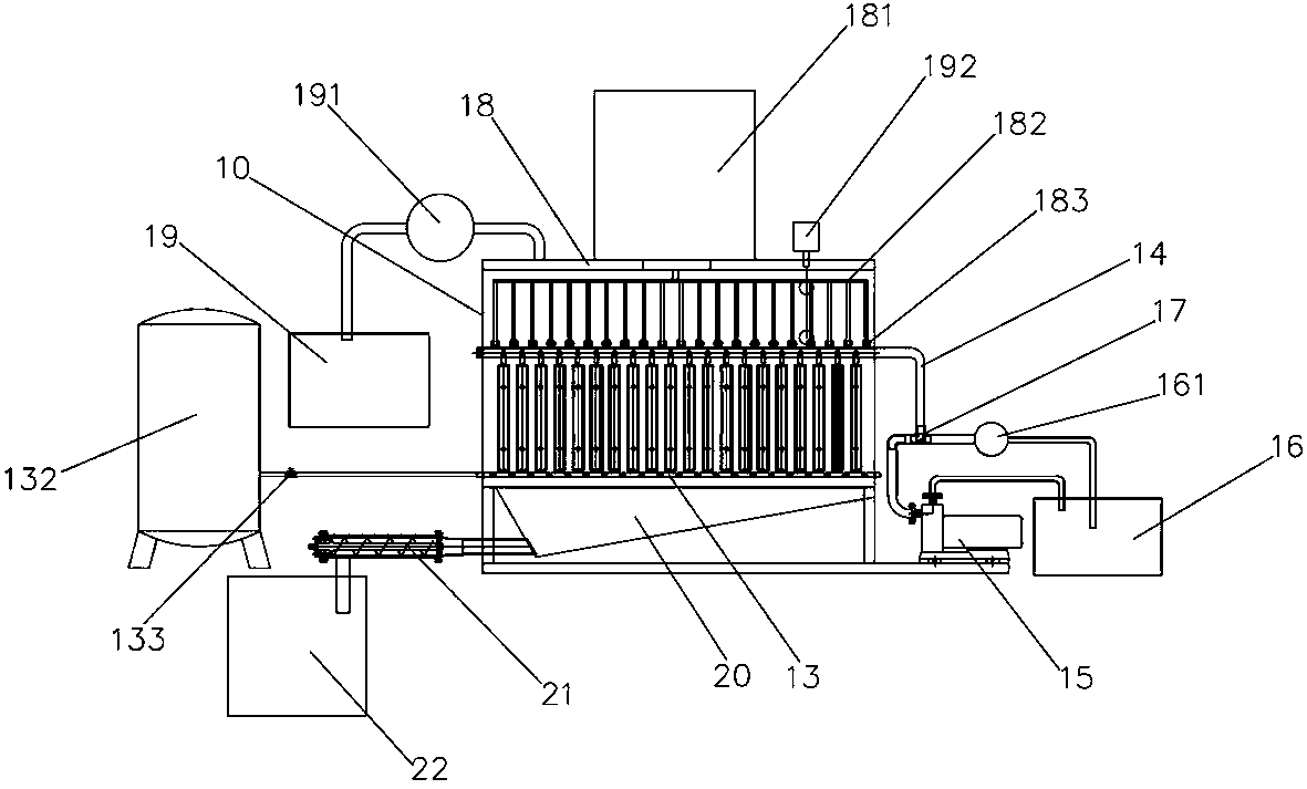
[0026] Embodiment 1, a sludge screw pump 21 is arranged on one side of the sludge hopper 20, and the sludge screw pump 21 is connected to the sludge hopper 20, and a sludge tank 22 is also arranged on the side of the sludge hopper 20, The sludge hopper 20 communicates with the sludge tank 22 through a sludge screw pump 21, and after concentration, the sludge sinks into the sludge bucket 20, and the sludge is sent out to the sludge tank 22 by the sludge screw pump 21;

Embodiment 2

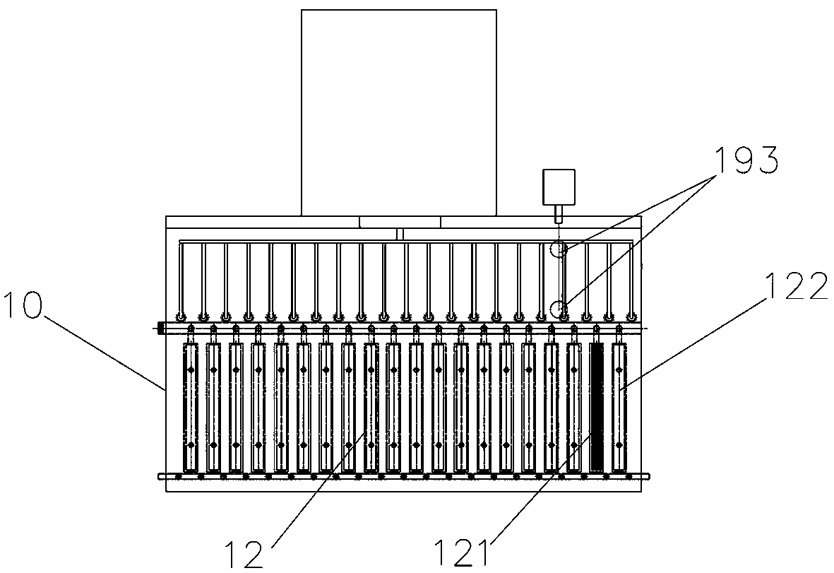
[0027] Embodiment 2, one end of the air outlet pipe 13 is fixed on the side plate of the sewage tank 10, and the other end passes through the side plate of the sewage tank 10 to connect with the gas storage tank 132, and a valve is arranged on the air outlet pipe 13 outside the sewage tank 10 Switch 133, the gas explosion pipe 131 is provided with a plurality of ventilation holes, when the concentrator is working, the valve switch 133 can be opened, and the gas explosion pipe 131 rushes out the high-speed airflow from the ventilation holes, so that the sewage flows on the surface of the nano-ceramic membrane 121, and the water flow is strengthened. Part passes through the efficiency of the nano-ceramic membrane 121;

Embodiment 3

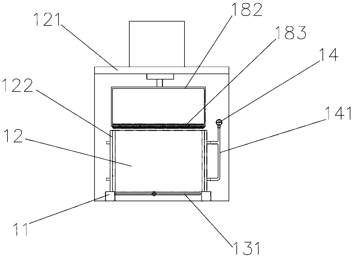
[0028] Embodiment 3, a three-way switching valve 17 is arranged between the filtrate water pipe 14 and the self-priming magnetic drive pump 15 and the clean water pool 16, and the filtrate water pipe 14 is respectively connected to the self-priming magnetic drive pump 15 through the three-way switching valve 17 1. Clean water pool 16, the self-priming magnetic drive pump 15 is connected to the clean water pool 16 through a pipeline, and the negative pressure generated by the self-priming magnetic drive pump 15 absorbs the water in the ceramic plate 12, and the power consumption is low, accounting for Small area, low operating cost, high sludge concentration efficiency;


PUM


Abstract

The invention discloses a sludge negative-pressure ceramic membrane concentration integrated machine. The machine comprises a sewage tank and a sludge hopper arranged at the bottom of the sewage tank,wherein a bracket is arranged on a bottom plate of the sewage tank, a plurality of ceramic plates with internal transverse hollow structures are installed on the bracket, a nano ceramic membrane anda nano ceramic membrane protection cover are arranged at the two transverse ends of each ceramic plate respectively, and the lower portion of the bottom of each ceramic plate is provided with an air outlet pipe; aeration pipes are horizontally arranged on the corresponding air outlet pipe below the portion between every two adjacent ceramic plates in the directions of the ceramic plates; a filtrate water pipe is arranged above one end of each ceramic plate, one end of each filtrate water pipe is fixed to a side plate of the sewage tank, and the other end of each filtrate water pipe penetratesthrough the corresponding side plate of the sewage tank and is separately connected with a self-suction type magnetic driving pump and a clean water pond; the filtrate water pipes penetrate through the nano ceramic membrane protection covers and the nano ceramic membranes through branch pipes and are communicated with the insides of the ceramic plates. The provided sludge negative-pressure ceramicmembrane concentration integrated machine aims at achieving the purposes of high concentration efficiency and low cost.

Description

technical field [0001] The invention relates to a sludge thickening machine, in particular to a sludge negative pressure ceramic membrane thickening integrated machine. Background technique [0002] At present, ordinary sludge thickening in the market is generally adopted as a concentration tank for gravity concentration. The construction cost of the concentration tank is high, the floor area is large, the sludge concentration time is long, and the efficiency is low. It is not suitable for large-scale sludge treatment plants. Some also use screw stackers for sludge concentration, but they need to add chemicals, the concentration efficiency is low, the concentration of sludge is unstable after concentration, and the SS content in the filtrate is high, so it cannot be discharged directly. Contents of the invention [0003] The object of the present invention is to provide a sludge negative pressure ceramic membrane thickening integrated machine to solve the problems raised i...

Claims


Application Information

Patent Timeline
Patent Type & Authority Applications(China)
IPC IPC(8): C02F11/121C02F11/00
CPCC02F11/00C02F11/121
Inventor 曾从根邹忠华
Owner 曾从根
Why Eureka
Try Eureka