Device for realizing laser precise positioning of tunnel drilling position and construction method
A drilling position and precise positioning technology, applied in tunnels, mining equipment, earthwork drilling and mining, etc., can solve problems such as dim light, time-consuming, poor construction environment, etc.
- Summary
- Abstract
- Description
- Claims
- Application Information
AI Technical Summary
Problems solved by technology
Method used
Image
Examples
Embodiment 1
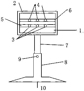
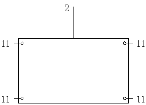
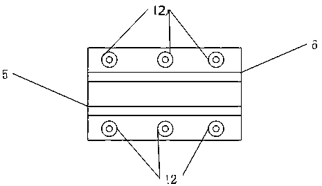
[0023] As introduced in the background technology, in the construction of tunnel blasting and excavation, it often takes a lot of time and money to repeatedly locate the drilling position. The accuracy directly affects the blasting effect, and it is easy to cause problems such as over-excavation and under-excavation. In order to solve the above technical problems, this application proposes the following figure 1 The shown device for realizing precise laser positioning of the tunnel drilling position includes a laser box 1 and a laser box fixing device 2, and the laser box fixing device 2 is provided with a parallel laser line chute 5 and a laser point chute 6. The laser line chute 5 is provided with three laser line emitters 3, the laser point chute 6 is provided with three laser point emitters 4, the laser line chute 5 and the laser point chute 6 is provided with a sliding hole along the groove, the laser line transmitter 3 and the laser point transmitter 4 are respectively c...
Embodiment 2
[0026] This embodiment is refined on the basis of the above embodiments, that is, figure 1 As shown, the supporting device includes a round rod 7 , a sleeve 8 and a base 10 , one end of the round rod 7 is placed in the sleeve 8 and connected with the sleeve 8 through a positioning bolt 9 . During the telescopic adjustment, after the adjustment is completed, the round rod 7 and the sleeve 8 are fixed by the positioning bolts.
Embodiment 3
[0028] This embodiment adopts a support device structure different from that of Embodiment 2 on the basis of Embodiment 1, such as Figure 4 As shown, the supporting device includes an outer cylinder 21, an upper rod 22, a lower rod 23 and a base 10, the bottom of the lower rod is fixed on the base, one end of the upper rod 22 and the lower rod 23 are respectively placed in the outer cylinder 21 and the upper rod 22 1. The lower rod 23 is connected to the outer cylinder 21 by threads, and the directions of the threads on the upper rod 22 and the lower rod 23 are opposite. When adjusting the height, fix the base with your feet, hold the upper rod with one hand, and turn the outer cylinder with the other hand to achieve height adjustment. Adopting this structure, the adjustable precision of its height is high.
PUM
 Abstract
Description
Claims
Application Information
 - R&D
- Intellectual Property
- Life Sciences
- Materials
- Tech Scout
- Unparalleled Data Quality
- Higher Quality Content
- 60% Fewer Hallucinations
Browse by: Latest US Patents, China's latest patents, Technical Efficacy Thesaurus, Application Domain, Technology Topic, Popular Technical Reports.
© 2025 PatSnap. All rights reserved.Legal|Privacy policy|Modern Slavery Act Transparency Statement|Sitemap|About US| Contact US: help@patsnap.com


