Engine rotational inertia measuring device

A technology of measuring device and moment of inertia, applied in the direction of measuring device, machine/structural component test, static/dynamic balance test, etc., can solve problems such as poor stability, low measurement accuracy, poor adaptability, etc., and achieve good elasticity and guarantee The effect of transmission quality and precision, easy assembly and disassembly

Active Publication Date: 2019-04-12
CHINA NAT PETROLEUM CORP CHUANQING DRILLING ENG CO LTD +1
View PDF12 Cites 3 Cited by
  • Summary
  • Abstract
  • Description
  • Claims
  • Application Information

AI Technical Summary

Problems solved by technology

[0007] The purpose of the present invention is to solve the problems of low measurement accuracy, poor stability and poor adaptability in the above-mentioned prior art, and to provide a measuring device for the moment of inertia of the engine. The present invention can effectively improve the measurement accuracy of the moment of inertia of the engine, and has good stability and Strong adaptability

Method used


Image

  • Engine rotational inertia measuring device
  • Engine rotational inertia measuring device
  • Engine rotational inertia measuring device

Examples


Embodiment 1

[0041] In describing the present invention, it should be understood that the terms "upper", "lower", "inner", "outer", "top", "bottom", "end", "front view", "side view", " The orientations or positional relationships indicated by "overlooking", "symmetrical", etc. are based on the orientations or positional relationships shown in the drawings, and are only for the convenience of describing the present invention and simplifying the description, and should not be construed as limiting the present invention.

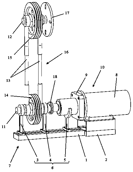
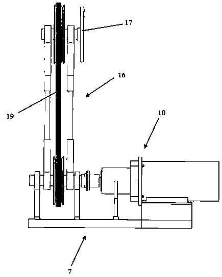
[0042] As a preferred embodiment of the present invention, it discloses a measuring device for moment of inertia of an engine, which is characterized in that it includes a body 7, a drive mechanism 10, a belt drive assembly 16 and a connecting flange 17; the body 7 includes a base and The support member 6 installed on the upper end of the base; the drive mechanism 10 includes a motor 8 and a reducer 9, and the drive mechanism 10 is placed on the base; the belt drive assembly...

Embodiment 2

[0044] As the best embodiment of the present invention, such as Figure 1 to Figure 6 As shown, the engine moment of inertia measuring device of the present invention includes a body 7, a drive mechanism 10, a belt drive assembly 16 and a connecting flange 17;

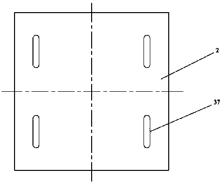
[0045] The body 7 includes a base A1, a base B2 and a support member 6. The base A1 and the base B2 are arranged adjacent to each other, and the connection and detachment of the two bases can be realized by bolts. The upper end of the base B2 is provided with four Fixed waist-shaped hole 37, the support member 6 includes support seat one 3, support seat two 4 and support seat three 5, all installed on the base A1;

[0046] The drive mechanism 10 includes a motor 8 and a reducer 9, the output end of the motor 8 is connected in transmission with the reducer 9, and the base of the motor 8 and the base B2 are adjustable connected through the waist-shaped hole 37, which can be adjusted according to the actual situation. Ad...


PUM


Abstract

The invention discloses an engine rotational inertia measuring device. The engine rotational inertia measuring device comprises a machine body, a driving mechanism, a belt transmission assembly and aconnecting flange connected with an output end flange of an engine to be measured; the machine body comprises two adjacently arranged bases and three supporting seats; the driving mechanism comprisesa motor and a reducer which are connected in a transmission mode, and is placed on the bases and the supporting seats; the belt transmission assembly comprises a belt transmission mechanism, a belt tensioning mechanism and two rotating shafts, the two rotating shafts can be rotatably connected with two belt pulleys and the belt tensioning mechanism through four bearings, the first rotating shaft is coaxially and fixedly connected with the output end of the reducer, and the second rotating shaft is fixedly disposed at the center of the connecting flange. The power output by the driving mechanism can be transmitted to the output end flange of the engine to be measured under the action of the belt transmission assembly, and by measuring the change conditions of the rotational speed torque ofan engine output shaft, the rotational inertia of the engine to be measured can be accurately measured. The engine rotational inertia measuring device has a compact structure, convenient assembly anddisassembly, high practicability and convenient popularization and use.

Description

technical field [0001] The invention relates to the technical field of industrial test and evaluation, in particular to a device for on-site measurement of the overall moment of inertia of the rotary moving parts of the engine. Background technique [0002] At present, the detection and evaluation of engine performance at home and abroad are mostly completed in special engine laboratories, which require special instruments, equipment and venues, and the test period is long and the cost is high. No-load dynamometer technology is a detection method that can quickly, conveniently and accurately evaluate the performance of the engine. It can detect the working condition of the engine without transporting it from the workplace to the laboratory. [0003] The moment of inertia of the engine is not only a key parameter necessary for the no-load dynamometer of the engine, but also a necessary parameter for obtaining the instantaneous torque of the engine, the compression pressure of...

Claims


Application Information

Patent Timeline
Patent Type & Authority Applications(China)
IPC IPC(8): G01M1/10
CPCG01M1/10
Inventor 敬佳佳张志东张祥来陈琅王文权徐友红陈瑞峰吴明扬胡燕
Owner CHINA NAT PETROLEUM CORP CHUANQING DRILLING ENG CO LTD
Why Eureka
Try Eureka