A High Precision Rogowski Coil

A Rogowski coil, high-precision technology, used in coils, electrical components, voltage/current isolation, etc., can solve problems such as inconvenient operation and long adjustment process, and achieve high practicability, improved position error and accuracy, and improved measurement accuracy. Effect

Active Publication Date: 2020-12-29
JIANGYIN SPARK ELECTRONICS TECH
View PDF21 Cites 0 Cited by
  • Summary
  • Abstract
  • Description
  • Claims
  • Application Information

AI Technical Summary

Problems solved by technology

It ensures that the central axis of the conductor coincides well with the central axis of the Rogowski coil by setting two pairs of up, down, left and right, a total of four compensation coils, but this makes the adjustment process relatively long and inconvenient to operate

Method used


Image

  • A High Precision Rogowski Coil
  • A High Precision Rogowski Coil
  • A High Precision Rogowski Coil

Examples


Embodiment 1

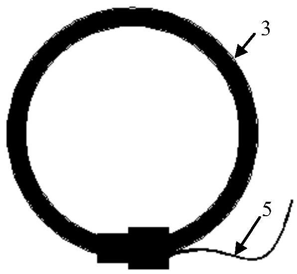
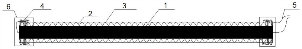
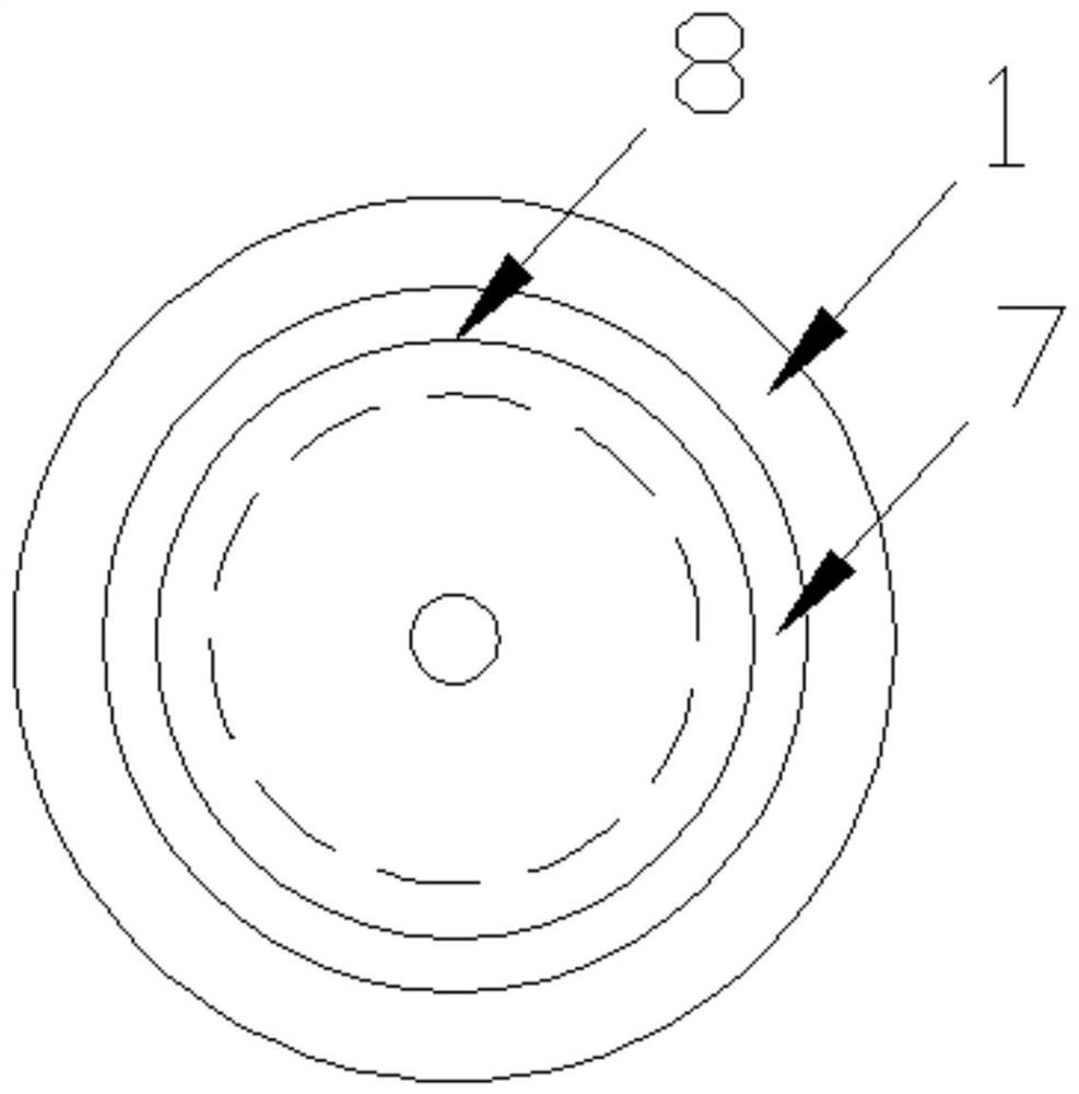
[0029] Such as Figure 1 to Figure 4 shown (for ease of illustration, figure 2 The flexible skeleton is not shown), the present invention is a high-precision Rogowski coil, comprising an annular body composed of an ignition wire 1, an enameled wire 2 and a silicone tube 3 arranged sequentially from the inside to the outside, and the enameled wire 2 is wound on the ignition wire 1 , the two ends of the ignition wire 1, the enameled wire 2 and the silicone tube 3 are connected through the joint 6, and the compensation coil 4 and the lead wire 5 are arranged in the joint 6, and one end of the compensation coil 4 is connected with the enameled wire 2, and the other end is connected with the lead wire 5; A flexible skeleton 7 is arranged on the inner side of the ring of the live wire 1, and a wire centering mechanism is fixedly arranged on the flexible skeleton 7. The wire centering mechanism includes a conical housing 8 fixed on the flexible framework 7, the large end of the con...

Embodiment 2

[0031] The difference from Embodiment 1 is that, as Figure 5 , Figure 6 As shown, the wire centering mechanism includes two pairs of clamping rods 9 fixed on the flexible skeleton 7, and the dimensions and specifications of all the clamping rods 9 are the same; one end of all the clamping rods 9 is fixed on the inner ring of the flexible skeleton 7, and all the clamping rods 9 The other ends of the coils are fixedly connected to each other and the connection point is located on the central axis of the annular Rogowski coil.

Embodiment 3

[0033] The difference from Embodiment 1 is that, as Figure 7 As shown, the wire centering mechanism includes two sections of elastic sliver 10 fixed on the inner side of the ring of the flexible skeleton 7, and the elastic sliver 10 is in a semi-circular shape; four pressure sensors are arranged in the elastic sliver 10 in a central circular array of Rogowski coils. 11. The pressure sensor 11 is fixed on the ring wall of the inner ring of the flexible skeleton 7 .


PUM


Abstract

The invention discloses a high-precision Rogowski coil, which comprises an annular body composed of an ignition wire, an enameled wire, and a silicone tube arranged in order from the inside to the outside. The enameled wire is wound around the ignition wire, and the two ends of the ignition wire and the enameled wire are connected by joints, and compensation coils and lead wires are arranged in the joints. One end of each compensation coil is connected to the enameled wire, and the other end is connected to the lead wire. The ignition wire is provided with a flexible frame on the ring-shaped inner side, and a wire centering mechanism is fixedly arranged on the flexible frame. The invention can ensure that the central axis of the wire coincides with the central axis of the Rogowski coil bythe conical housing or the arrangement of the clamping rods arranged in a tapered shape, thereby avoiding the phase error. The new Rogowski coil of this design has improved a lot in position error andaccuracy, and is also very practical. The complexity of the structure does not increase the process flow compared to the Rogowski coil in the prior art, so the invention will be a qualitative breakthrough in power measurement, contributing to the power system.

Description

technical field [0001] The invention relates to a high-precision Rogowski coil. Background technique [0002] With the development of social economy, electric energy, as the main energy source in modern society, is more and more closely related to people's life and production and construction. With the rapid development of EHV and UHV power transmission and transformation technologies, the capacity and quantity of power equipment have increased significantly, and the scale of power grids has gradually expanded. The operation of the modern power system must not only ensure the quality of qualified power supply, but also ensure the stable and reliable power generation and power supply capacity. The power transformer is one of the most important equipment in the power system, and it is particularly important to improve the operation reliability of the power transformer. On-line monitoring of transformers can detect transformer faults in time and carry out early warning of acc...

Claims


Application Information

Patent Timeline
Patent Type & Authority Patents(China)
IPC IPC(8): G01R15/18H01F5/02H01F5/04
CPCG01R15/18H01F5/02H01F5/04
Inventor 杨友振
Owner JIANGYIN SPARK ELECTRONICS TECH
Why Eureka
Try Eureka