
Gradient echo sequence setting method, magnetic resonance imaging system scanning method, equipment and medium

A gradient echo and gradient technology, applied in the field of medical imaging, can solve problems such as affecting image quality, shortening TE, TR space, etc., to shorten the echo time and improve the display effect.

Active Publication Date: 2021-03-09
SHANGHAI UNITED IMAGING HEALTHCARE
View PDF11 Cites 0 Cited by
  • Summary
  • Abstract
  • Description
  • Claims
  • Application Information

AI Technical Summary

Problems solved by technology

[0004] Taking the Balanced Steady-State Free Processing (BSSFP) sequence as an example, the measures adopted to reduce TE and TR are ramp sampling (Ramp Sampling), which is carried out by making full use of the ramp-up period of the readout gradient. The reading of the signal, but the signal collected by the RampSampling measure is nonlinear, and linear sampling data needs to be obtained by interpolation. Therefore, the image reconstruction of the sampled data collected by the RampSampling measure requires a better interpolation function, and the interpolation operation There is a risk of affecting image quality
In addition, the RampSampling measure has limited space to shorten TE and TR

Method used


Image

  • Gradient echo sequence setting method, magnetic resonance imaging system scanning method, equipment and medium
  • Gradient echo sequence setting method, magnetic resonance imaging system scanning method, equipment and medium
  • Gradient echo sequence setting method, magnetic resonance imaging system scanning method, equipment and medium

Examples


Embodiment 1

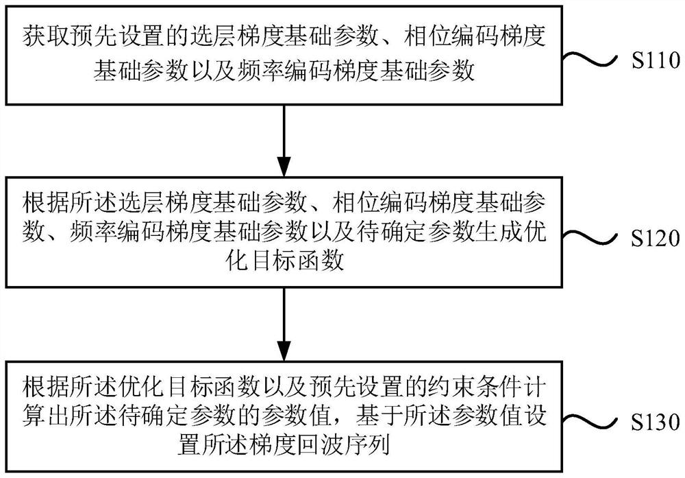
[0042] Figure 1a It is a flow chart of a gradient echo sequence setting method provided by Embodiment 1 of the present invention. This embodiment is applicable to the situation when a gradient echo sequence is set up for scanning of magnetic resonance imaging. The method can be executed by a gradient echo sequence setting device, and the gradient echo sequence setting device can be implemented in software and / or hardware, for example, the gradient echo sequence setting device can be configured in a computer device. Such as Figure 1a As shown, the method includes:

[0043] S110. Obtain preset basic layer selection gradient parameters, basic phase encoding gradient parameters, and basic frequency encoding gradient parameters.

[0044] The three-dimensional spatial positioning of MRI scanning imaging is realized by applying three mutually perpendicular controllable linear gradient magnetic fields. According to the different positioning functions, the three gradient fields are...

Embodiment 2

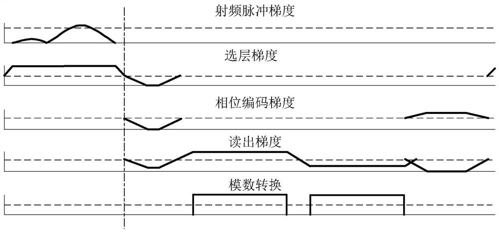
[0064] figure 2 It is a flowchart of a gradient echo sequence setting method provided by Embodiment 2 of the present invention. This embodiment is further optimized on the basis of the foregoing embodiments. Such as figure 2 As shown, the method includes:

[0065] S210. Obtain preset basic layer selection gradient parameters, basic phase encoding gradient parameters, and basic frequency encoding gradient parameters.

[0066] S220, create a function max{min[r 1 G s +G sd , G ped , G rod + r 3 G ro ]} as the optimization objective function.

[0067] In this embodiment, the optimization objective function is embodied as:

[0068] max{min[r 1 G s +G sd , G ped , G rod + r 3 G ro ]}

[0069] Among them, r 1 is the to-be-determined climb time of the layer-selection re-gathering gradient, r 3 is the to-be-determined ramp-up time of the readout pre-dispersion gradient, G s is the basic amplitude of the layer selection gradient, G sd Amplitude to be determined ...

Embodiment 3

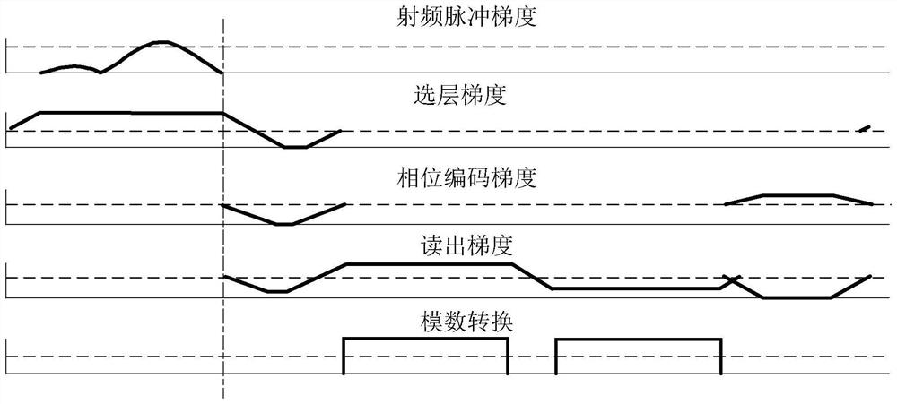
[0084] image 3 It is a flow chart of a scanning method of a magnetic resonance imaging system provided by Embodiment 1 of the present invention. This embodiment is applicable to the case of using a magnetic resonance imaging system to perform rapid scans on a subject, wherein the magnetic resonance imaging system includes radio frequency transmitting coils and gradient coils. The method can be executed by a scanning device of a magnetic resonance imaging system, and the scanning device of the magnetic resonance imaging system can be realized by software and / or hardware, for example, the scanning device of the magnetic resonance imaging system can be configured in a computer device. Such as image 3 As shown, the method includes:

[0085] S310, setting scan parameters related to the MRI scan.

[0086] In this embodiment, the scanning parameters include radio frequency pulse parameters and gradient pulse parameters, and the gradient pulse parameters include layer selection g...


PUM


Abstract

The embodiment of the present invention discloses a sequence setting method, a magnetic resonance imaging system scanning method, equipment and media. The sequence setting method includes: acquiring pre-set layer selection gradient basic parameters, phase encoding gradient basic parameters and frequency encoding gradient basic parameters parameters; according to the layer selection gradient basic parameters, phase encoding gradient basic parameters, frequency encoding gradient basic parameters and parameters to be determined, the optimization objective function is generated; according to the optimization objective function and preset constraints, the parameter values ​​​​of the parameters to be determined are calculated, and based on the parameters Value sets the gradient echo sequence. The parameter values ​​of the sequence are calculated by optimizing the objective function and constraint conditions, so that the setting of the sequence makes full use of the falling time of the layer selection gradient and the rising time of the readout gradient, shortens the echo time in the sequence, and improves the display effect of the image .

Description

technical field [0001] Embodiments of the present invention relate to the technical field of medical imaging, and in particular to a gradient echo sequence setting method, a magnetic resonance imaging system scanning method, equipment and media. Background technique [0002] Gradient echo is an echo signal of MRI. Conventional gradient echo (GRE) sequence is composed of radio frequency pulse, slice selection gradient, phase encoding gradient, readout gradient and NMR signal. Conventional GRE sequence has two characteristics: (1) The excitation angle of radio frequency pulse is less than 90° °; (2) The generation of echo depends on the switching of the readout gradient field (that is, the frequency encoding gradient field). Generally, the time interval between the small-angle pulse midpoint and the echo midpoint is defined as echo time (TE), and the time interval between two adjacent small-angle pulse repetitions is defined as repetition time (TR). [0003] The GRE sequence...

Claims


Application Information

Patent Timeline
Patent Type & Authority Patents(China)
IPC IPC(8): G01R33/561
CPCG01R33/5615
Inventor 龚小茂
Owner SHANGHAI UNITED IMAGING HEALTHCARE
Learn More