Dustproof computer case convenient for heat dissipation

A computer mainframe and mainframe technology, applied in electrical digital data processing, digital processing power distribution, instruments, etc., can solve the problems of reducing the service life of the mainframe, dust on the case, loss of internal components of the computer, etc., to achieve convenient fixed installation and The effect of dismantling, expanding the air flow speed, and accelerating the gas flow

Inactive Publication Date: 2019-04-12
赖成凤
4 Cites 4 Cited by

AI-Extracted Technical Summary

Problems solved by technology

Although there are many types and quantities of industrial computers currently on the market, the heat dissipation effect of the main case of most industrial computers is not very good during use. High and lead to crash, which seriously affects the use, and the existing main case of the computer often needs to disassemble the entire main case to clean the dust when cleaning the internal dust, which is very troublesome to use
As a part of computer accessories, the computer case is mainly used to place and fix various computer accessories, and play a role of support and protection. Since the case is not like the CPU, graphics card, motherboard and other accessories that can quickly improve the performance...

Method used

Working principle of the present invention and use process: during use, by arranging heat dissipation grid 2, first heat dissipation fan 5, air vent 15 and second heat dissipation fan 11, expanded heat dissipation channel and air velocity, accelerated heat dissipation Efficiency prolongs the service life of the host. By setting the first damping spring 8, the second damping spring 13 and the third damping spring 14, the stable installation of the fixed frame can be realized if it is shaken during the transportation process, preventing the host from The computer components inside the box are damaged due to impact. By setting the first dust-proof net 3, the second dust-proof net 16 and the air-drying net 12, the air flowing in the installation cavity 6 can be dried to prevent moisture. To prevent the com...

Abstract

The invention discloses a dustproof computer case convenient for heat dissipation. The dustproof computer case comprises a mainframe box main body, a heat dissipation grating, a first dustproof net, aU-shaped baffle, a first heat dissipation fan, a mounting cavity, a fixing frame body, a first damping spring, a partition plate, a mounting hole, a second heat dissipation fan, an air drying net, asecond damping spring, a third damping spring, a ventilation opening, a second dustproof net, a first mounting plate, a second mounting plate, a third mounting plate and a fourth mounting plate. A plurality of clamping holes are evenly formed in the third mounting plate and the fourth mounting plate, clamping blocks are fixedly mounted at the ends of the first mounting plate, the second mounting plate, the third mounting plate and the fourth mounting plate and matched with the clamping holes, movable baffles are arranged on the front side and the rear side of the fixing frame, and a pluralityof strip-shaped heat dissipation holes are evenly formed in the movable baffles. The dustproof computer case has a good dustproof effect, a heat dissipation channel is expanded, the heat dissipation efficiency is improved, and the service life of a host is prolonged.

Application Domain

Technology Topic

Image

  • Dustproof computer case convenient for heat dissipation
  • Dustproof computer case convenient for heat dissipation
  • Dustproof computer case convenient for heat dissipation

Examples

  • Experimental program(1)

Example Embodiment

[0023] The technical solutions in the embodiments of the present invention will be clearly and completely described below in conjunction with the accompanying drawings in the embodiments of the present invention. Obviously, the described embodiments are only a part of the embodiments of the present invention, rather than all the embodiments. Based on the embodiments of the present invention, all other embodiments obtained by those of ordinary skill in the art without creative work shall fall within the protection scope of the present invention.
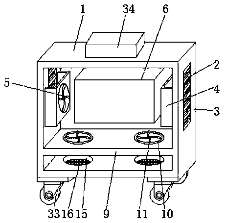
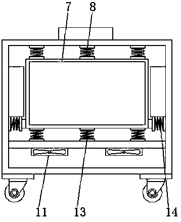
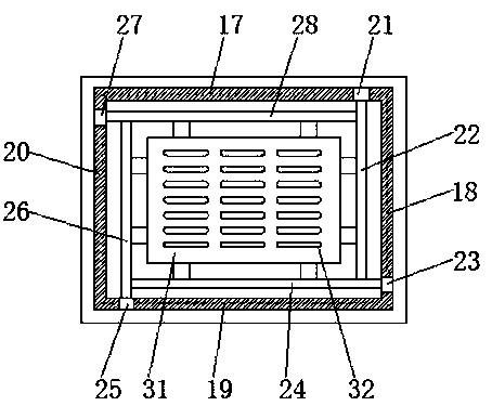
[0024] See Figure 1-5 , The present invention provides a technical solution: a computer mainframe that is convenient for heat dissipation and dustproof, comprising a mainframe main body 1, a heat dissipation grille 2 is provided on both sides of the mainframe mainframe body 1, and a second heat dissipation grille 2 A dust-proof net 3, U-shaped baffles 4 are provided on the inner walls of both sides of the main box body 1, both U-shaped baffles 4 are installed with a first cooling fan 5, and two first cooling fans 5 are provided There is a mounting cavity 6, a fixed frame 7 is provided inside the mounting cavity 6, a number of first damping springs 8 are provided between the top of the fixed frame 7 and the top inner side of the main box body 1, and the fixed frame 7 is provided below There is a partition 9, a pair of mounting holes 10 are opened on the partition 9, a second radiating fan 11 is matched and installed in the mounting hole 10, the bottom of the second radiating fan 11 is covered with an air drying net 12, and the top of the partition 9 is connected to A number of second damping springs 13 are provided between the bottom of the fixed frame 7, and a number of third damping springs 14 are provided between the bottoms on both sides of the fixed frame 7 and the inner walls on both sides of the main box body 1. A pair of vents 15 are provided at the bottom of the main body 1, a second dust-proof net 16 is provided in the vents 15, and a first chute 17, a second chute 18, and a third chute 19 are sequentially provided on the inner side of the fixed frame 7 And the fourth sliding groove 20, the first sliding groove 17 is matched with a first sliding block 21, the first sliding block 21 is fixedly connected with a first mounting plate 22, and the second sliding groove 18 is matched with a second sliding block 23. , The second sliding block 23 is fixedly connected with the second mounting plate 24, the third sliding groove 19 is matched with a third sliding block 25, the third sliding block 25 is fixedly connected with the third mounting plate 26, and the fourth sliding groove 20 is A fourth sliding block 27 is matched, and the fourth sliding block 27 is fixedly connected with a fourth mounting plate 28. The first mounting plate 22, the second mounting plate 24, the third mounting plate 26 and the fourth mounting plate 28 are evenly provided There are several clamping holes 29. The ends of the first mounting plate 22, the second mounting plate 24, the third mounting plate 26 and the fourth mounting plate 28 are all fixedly installed with a clamping block 30, which matches the clamping hole 29 , The front and rear sides of the fixed frame 7 are provided with movable baffles 31, and the edges of the movable baffles 31 are respectively connected to the first mounting plate 22, the second mounting plate 24, the third mounting plate 26 and the fourth mounting plate 28 For fixed connection, a number of strip-shaped heat dissipation holes 32 are uniformly provided on the movable baffle 31, and universal wheels 33 are provided at the bottom four corners of the main box body 1.
[0025] The length of the heat dissipation grille 2 is slightly longer than the length of the U-shaped baffle 31. The strip heat dissipation holes 32 are arranged in an array disk on the movable baffle 31. The first dust-proof net 3 and the second dust-proof net 16 are both made of two layers of yarn The vent 15 is located directly under the second cooling fan 11, and the inner diameter of the vent 15 is larger than the inner diameter of the mounting hole 10. The top of the main box body 1 is provided with a blower 34, and the air outlet of the blower 34 is connected to The mounting cavity 6 is connected, the first cooling fan 5 and the second cooling fan 11 have four blades. The size of the first mounting plate 22, the second mounting plate 24, the third mounting plate 26 and the fourth mounting plate 28 Exactly the same.
[0026] The working principle and use process of the present invention: when in use, by setting the heat dissipation grille 2, the first heat dissipation fan 5, the vent 15 and the second heat dissipation fan 11, the heat dissipation channel and the air flow speed are enlarged, and the heat dissipation efficiency is increased. In order to improve the service life of the main unit, by setting the first damping spring 8, the second damping spring 13 and the third damping spring 14, the stable installation of the fixed frame can be realized if it is shaken during transportation, preventing the internal The computer components are damaged by impact. The first dust-proof net 3, the second dust-proof net 16 and the air drying net 12 can be arranged to dry the air flowing in the installation cavity 6, which has a moisture-proof effect and prevents the main cabinet The internal computer components are damaged by damp. By setting the first mounting plate 22, the second mounting plate 24, the third mounting plate 26, the fourth mounting plate 28 and the movable baffle 31, they are installed in cooperation with the clamping block 30 through the clamping hole 39, It is convenient for the fixed installation and disassembly of the internal components of the computer, convenient and quick to use, and prevents the internal components from shaking. The multiple strip vents 32 on the movable baffle 31 can increase the heat dissipation channel. In addition, the blower 34 can blow fresh cold air Into the installation cavity 6 to accelerate the gas flow, which can greatly improve the heat dissipation efficiency of the main box.
[0027] Although the embodiments of the present invention have been shown and described, those of ordinary skill in the art can understand that various changes, modifications, and substitutions can be made to these embodiments without departing from the principle and spirit of the present invention. And variations, the scope of the present invention is defined by the appended claims and their equivalents.

PUM

no PUM

Description & Claims & Application Information

We can also present the details of the Description, Claims and Application information to help users get a comprehensive understanding of the technical details of the patent, such as background art, summary of invention, brief description of drawings, description of embodiments, and other original content. On the other hand, users can also determine the specific scope of protection of the technology through the list of claims; as well as understand the changes in the life cycle of the technology with the presentation of the patent timeline. Login to view more.

Similar technology patents

High-frequency high-speed and high-density circuit board manufacturing process

InactiveCN110461100AIncrease air velocityImprove cooling speedPrinted circuit aspectsConductive material chemical/electrolytical removalCopper foilExternal energy
Owner:四川深北电路科技有限公司

Water-driven heat exchange enhanced type heating radiator

PendingCN110081504AIncrease air velocityImprove convective heat transfer coefficientLighting and heating apparatusSpace heating and ventilation detailsPipingAirflow
Owner:CHINA RAILWAY DESIGN GRP CO LTD

Classification and recommendation of technical efficacy words

  • Improve cooling efficiency
  • Increase air velocity

Ring insert for an air intake conduit for an internal combustion engine

InactiveUS7942139B1Increase air velocityDecrease air pressureMixing methodsGas modification by gas mixingInternal combustion engineLeading edge
Owner:MILE EDGE PLUS

Fan assembly

ActiveUS20120189439A1Increase air velocityIncrease speedPump componentsJet pumpsAirflowEngineering
Owner:DELTA ELECTRONICS INC

Venturi vortex and flow facilitating turbine

ActiveUS20200040870A1Increase air velocityFacilitate expulsionWind motor combinationsMachines/enginesTurbine bladeEngineering
Owner:MONTO MARK
Why Eureka
Try Eureka