A lateral high voltage device
A lateral high voltage, device technology, applied in the direction of semiconductor devices, electrical components, circuits, etc., can solve the problems of rising on-resistance and restricting applications, and achieve the effect of increasing the current in the non-saturation region and alleviating the impact.
- Summary
- Abstract
- Description
- Claims
- Application Information
AI Technical Summary
Problems solved by technology
Method used
Image
Examples
Embodiment 1
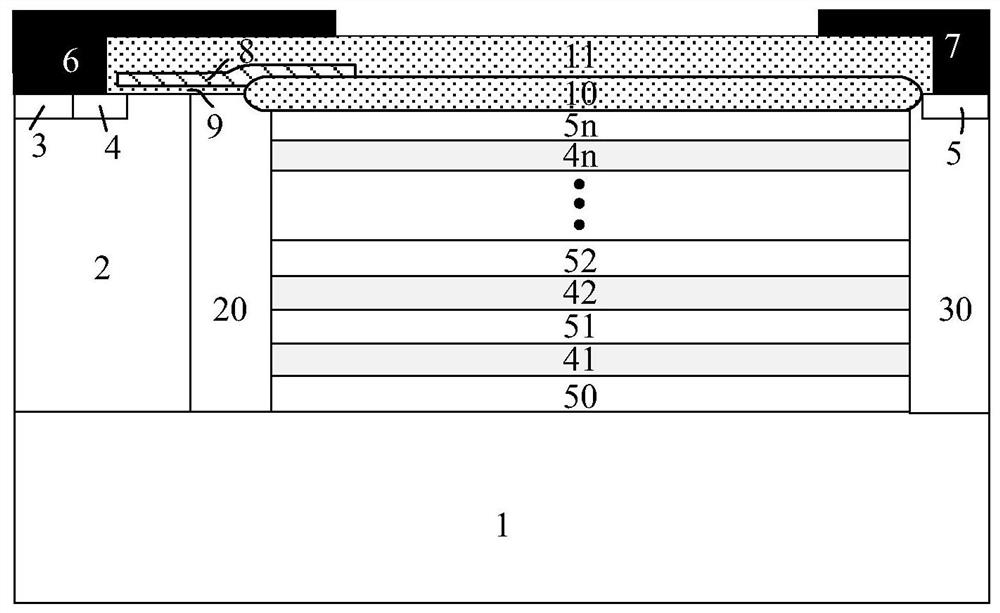
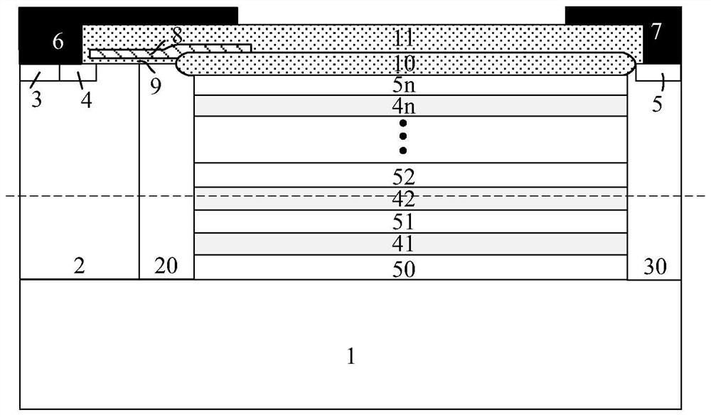
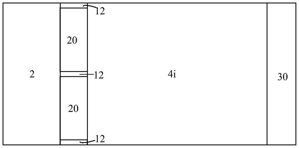
[0030] like figure 1As shown, an embodiment 1 of a lateral high voltage device, its cellular structure includes: a second conductivity type semiconductor substrate 1, a second conductivity type semiconductor 2 disposed on the upper end surface of the second conductivity type semiconductor substrate 1, disposed on The first conductivity type semiconductor drift region 50 on the upper end surface of the second conductivity type semiconductor substrate 1, the first conductivity type semiconductor drift region 50 is provided with stacked PN bars, and the PN bars include: disposed in the first conductivity type semiconductor drift region 50 The first layer of the second conductivity type buried layer 41, the first layer of the first conductivity type semiconductor 51 disposed on the upper surface of the first layer of the second conductivity type buried layer 41 in the first conductivity type semiconductor drift region 50, the first layer of the first conductivity type semiconductor...
Embodiment 2
[0039] like image 3 As shown, the difference between this example and Example 1 is that the source first-conductivity-type JFET implantation region 20 uses multiple implants to finally form a stacked structure of multiple JFET implantation regions, including the source first-layer first-conductivity-type JFET Injection region 21, source second layer first conductivity type JFET injection 22... source first mth layer first conductivity type JFET injection region 2m, m≥1; drain first conductivity type JFET injection region 30 adopts multiple injections to finally Form a stacked structure of multiple JFET implantation regions, including the first drain layer first conductivity type JFET implantation region 31, the drain second layer first conductivity type JFET implantation 32...the drain mth layer first conductivity type JFET implantation region 3m, m≥1.
[0040] In this embodiment, the concentration distribution of the JFET region in the first embodiment is further optimized,...
Embodiment 3
[0042] like Figure 4 and Figure 5 As shown, the difference between this example and Example 2 is that neither the source first conductivity type JFET injection region 20 nor the drain first conductivity type JFET injection region 30 in this example is placed on the semiconductor surface, and the drift region is close to the source The end surface and the surface close to the drain end are all low-concentration first conductivity type semiconductor drift regions 50, and the lower end surface is not limited, and can be as follows Figure 4 The lower surfaces of the first JFET implantation region 21 of the first conductivity type of the source electrode and the JFET implantation region 30 of the first conductivity type of the drain electrode are all in contact with the semiconductor substrate 1 of the second conductivity type. Figure 5 The lower surfaces of the source first layer JFET implantation region 21 of the first conductivity type and the drain first conductivity type ...
PUM
 Abstract
Description
Claims
Application Information
 - R&D
- Intellectual Property
- Life Sciences
- Materials
- Tech Scout
- Unparalleled Data Quality
- Higher Quality Content
- 60% Fewer Hallucinations
Browse by: Latest US Patents, China's latest patents, Technical Efficacy Thesaurus, Application Domain, Technology Topic, Popular Technical Reports.
© 2025 PatSnap. All rights reserved.Legal|Privacy policy|Modern Slavery Act Transparency Statement|Sitemap|About US| Contact US: help@patsnap.com


