Flying capacitor charging method and device

A technology for charging flying capacitors and capacitors, which is applied in the field of charging methods and devices for flying capacitors, can solve the problems of poor applicability and high circuit cost, and achieve the effects of strong applicability and cost reduction

Active Publication Date: 2019-04-12
HUAWEI DIGITAL POWER TECH CO LTD
View PDF5 Cites 15 Cited by
  • Summary
  • Abstract
  • Description
  • Claims
  • Application Information

AI Technical Summary

Problems solved by technology

thus figure 2 Applicability of the scenarios shown is not strong
[0009] To sum up, in the flying capacitor chargi

Method used


Image

  • Flying capacitor charging method and device
  • Flying capacitor charging method and device
  • Flying capacitor charging method and device

Examples


example 1

[0102] for Figure 6 The multi-level topology circuit shown can charge the flying capacitors (ie Ca and Cb) in the following manner.

[0103] Generally, the operation of the power electronic power circuit needs to be controlled by the controller, and the method for precharging the flying capacitor provided by the embodiment of the present application can also be regarded as being controlled and executed by the controller independent of the multilevel topology circuit. The power supply that powers the controller can be referred to as an auxiliary power supply. Generally, the auxiliary power supply can adopt a switching power supply circuit with a high voltage input and a low voltage output such as 12V or 24V.

[0104] S1: After the auxiliary source is turned on, control and close the switching devices T1b and T4b in each topology. Connect the output capacitor Cout in parallel with the flying capacitor Cb.

[0105] S2: Use a DC power supply (such as a flyback power supply), c...

example 2

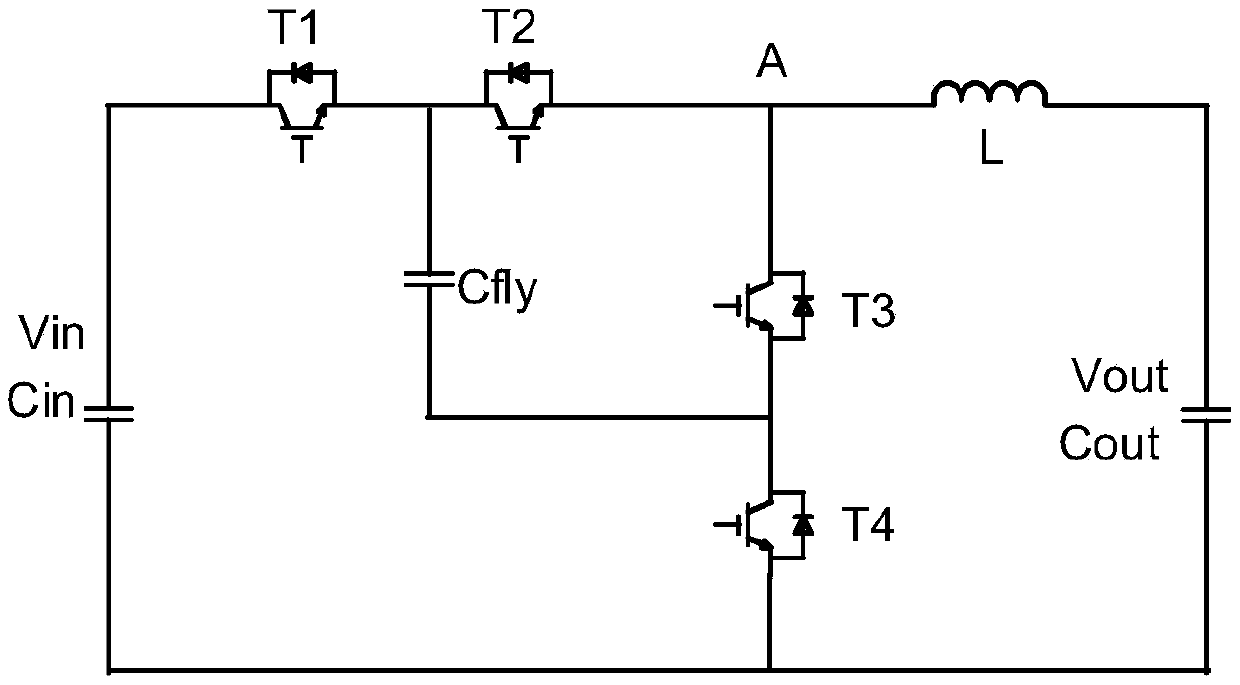
[0113] for Figure 4 The multi-level topology circuit shown can charge the flying capacitor (ie Cfly) in the following manner.

[0114] S1: After the auxiliary source is turned on, it controls the switching devices T1 and T4 in the closed topology circuit. Connect the input capacitor Cin in parallel with the flying capacitor Cfly.

[0115] S2: Use a DC power supply (such as a flyback power supply), connect the output of the power supply to both ends of the input capacitor Cin, and charge the input capacitor Cin and the flying capacitor Cfly connected in parallel. The charging target value is the flying capacitor Cfly The voltage during normal operation, that is, half of the DC source1 voltage.

[0116] S3: When the flying capacitor Cfly reaches the target value, disconnect T1 and T4, and disconnect the flying capacitor Cfly from the input capacitor Cin.

[0117] S4: continue to charge the input capacitor Cin, the target value is the voltage of DC source1.

[0118] S5: Afte...

example 3

[0123] for Figure 4 The multi-level topology circuit shown can charge the flying capacitor (ie Cfly) in the following manner.

[0124] S1: After the auxiliary source is turned on, it controls the switching devices T1 and T4 in the closed topology. Connect the input capacitor Cin in parallel with the flying capacitor Cfly.

[0125] S2: Use a DC power supply (such as a flyback power supply), connect the output of the power supply to both ends of the output capacitor Cout, and charge the three capacitors (ie Cin, Cfly, and Cout) connected in parallel. The target value of the charge is fly The voltage when the transcapacitor works normally, that is, half of the DC source1 voltage.

[0126] S3: When the flying capacitor Cfly reaches the target value, disconnect T1 and T4.

[0127] S4: continue to charge the output capacitor Cout and the input capacitor Cin, and the target value is the DC source1 voltage.

[0128] S5: After reaching the target value, stop charging, the voltage ...


PUM


Abstract

The invention provides a flying capacitor charging method and device which are applied to a multi-level topological circuit, so as to provide a flying capacitor charging scheme which is small in occupied area and high in applicability. The circuit is connected with an input power supply through a first switch and is connected with an output power supply through a second switch; the first end of afirst capacitor in the flying capacitor in the circuit is connected with the first electrode of a first semiconductor switch tube, while the second end is connected with the second electrode of a second semiconductor switch tube; the second electrode of the first semiconductor switch tube is connected with the first electrode of the second semiconductor switch tube through a second capacitor, wherein the second capacitor is an input capacitor, an output capacitor or another flying capacitor; and the method comprises the following steps of closing the first semiconductor switch tube and the second semiconductor switch tube, so that the first capacitor and the second capacitor are connected in parallel; charging the first capacitor and the second capacitor to a first set voltage value; disconnecting the first semiconductor switch tube and the second semiconductor switch tube; and charging the second capacitor to a second set voltage value.

Description

technical field [0001] The present application relates to the technical field of power electronics, in particular to a method and device for charging a flying capacitor. Background technique [0002] A DC-DC conversion circuit (referred to as a DCDC circuit) is a circuit that boosts or steps down a DC voltage. Its input and output are DC. DCDC circuits are widely used in energy storage, electric vehicles, new energy, power systems, electronic computers and other fields. The topological forms of DCDC circuits can be divided into two-level topologies and multi-level topologies according to the state of the output level. [0003] The multi-level topology is relative to the traditional two-level topology. The two-level topology means that the output level has only two states of 0 and 1. The multi-level topology means that the output level has at least three states. For example, the output voltage There are three states of 1, 1 / 2 and 0, which are called three-level topology, a...

Claims


Application Information

Patent Timeline
IPC IPC(8): H02J7/00H01M10/44H02M3/158
CPCH02J7/0072H02J7/0077H01M10/44H02M3/1582Y02E60/10H02M3/158H02J7/345H02M3/07H02J2207/20H02M1/0095H02M7/4837H02M3/1584
Inventor 姜一鸣
Owner HUAWEI DIGITAL POWER TECH CO LTD
Why Eureka
Try Eureka