Eureka AIR delivers breakthrough ideas for toughest innovation challenges, trusted by R&D personnel around the world.

System and method of millimeter wave attenuation measurement

An attenuation measurement, millimeter wave technology, applied in the transmission system, transmission monitoring, electrical components, etc., can solve the problem of out-of-synchronization between the external reference frequency of the lock-in amplifier and the frequency of the audio signal, the frequency jitter of the audio signal, and the detection noise of the lock-in amplifier at the receiving end Mutual crosstalk and other issues can be solved to solve the problem of out-of-synchronization between the external reference frequency and the audio signal frequency, stabilize the measurement circuit, and reduce the frequency jitter of the audio signal

Active Publication Date: 2019-04-12
BEIJING INST OF RADIO METROLOGY & MEASUREMENT
View PDF6 Cites 4 Cited by
  • Summary
  • Abstract
  • Description
  • Claims
  • Application Information

AI Technical Summary

Problems solved by technology

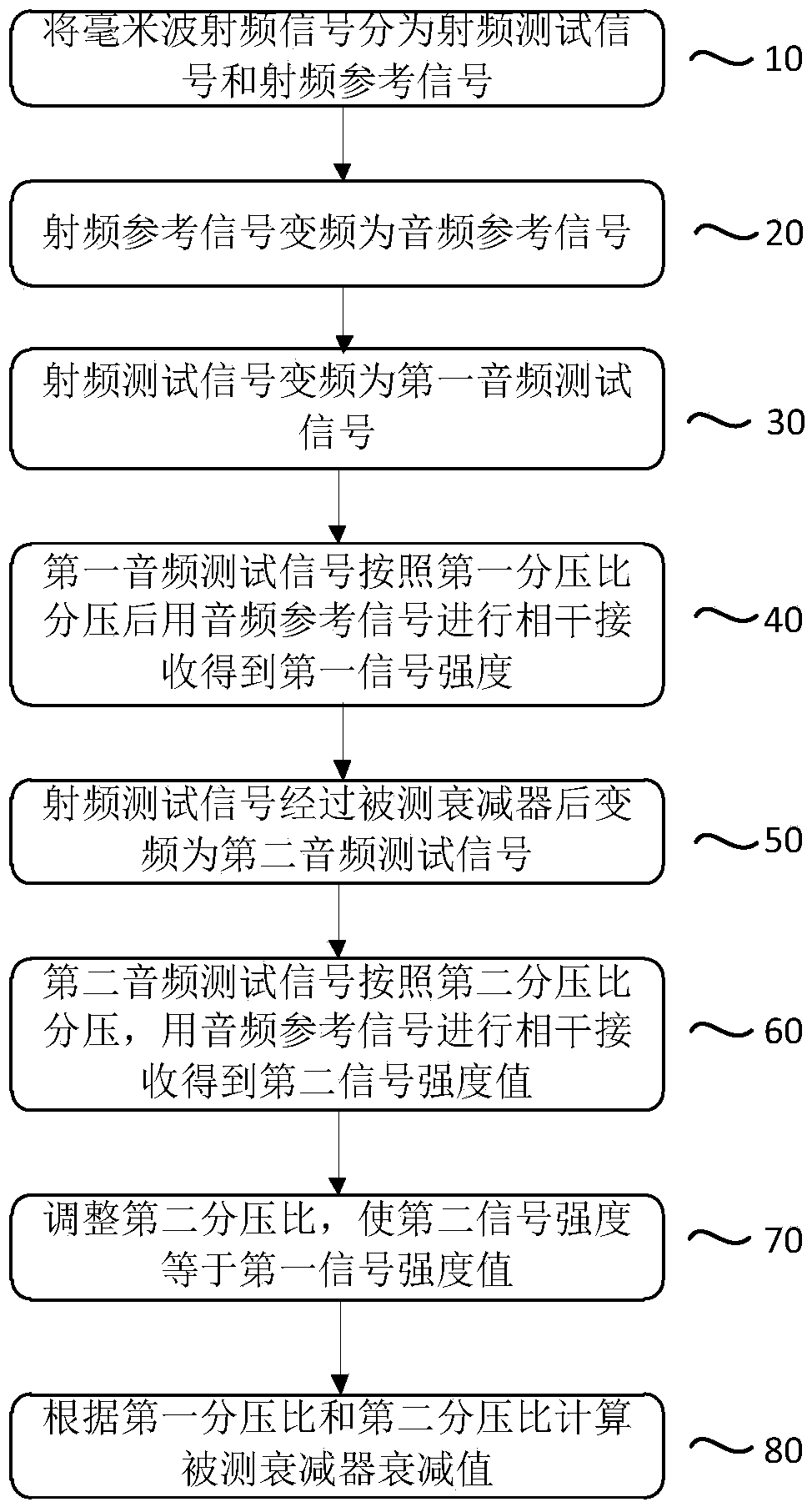
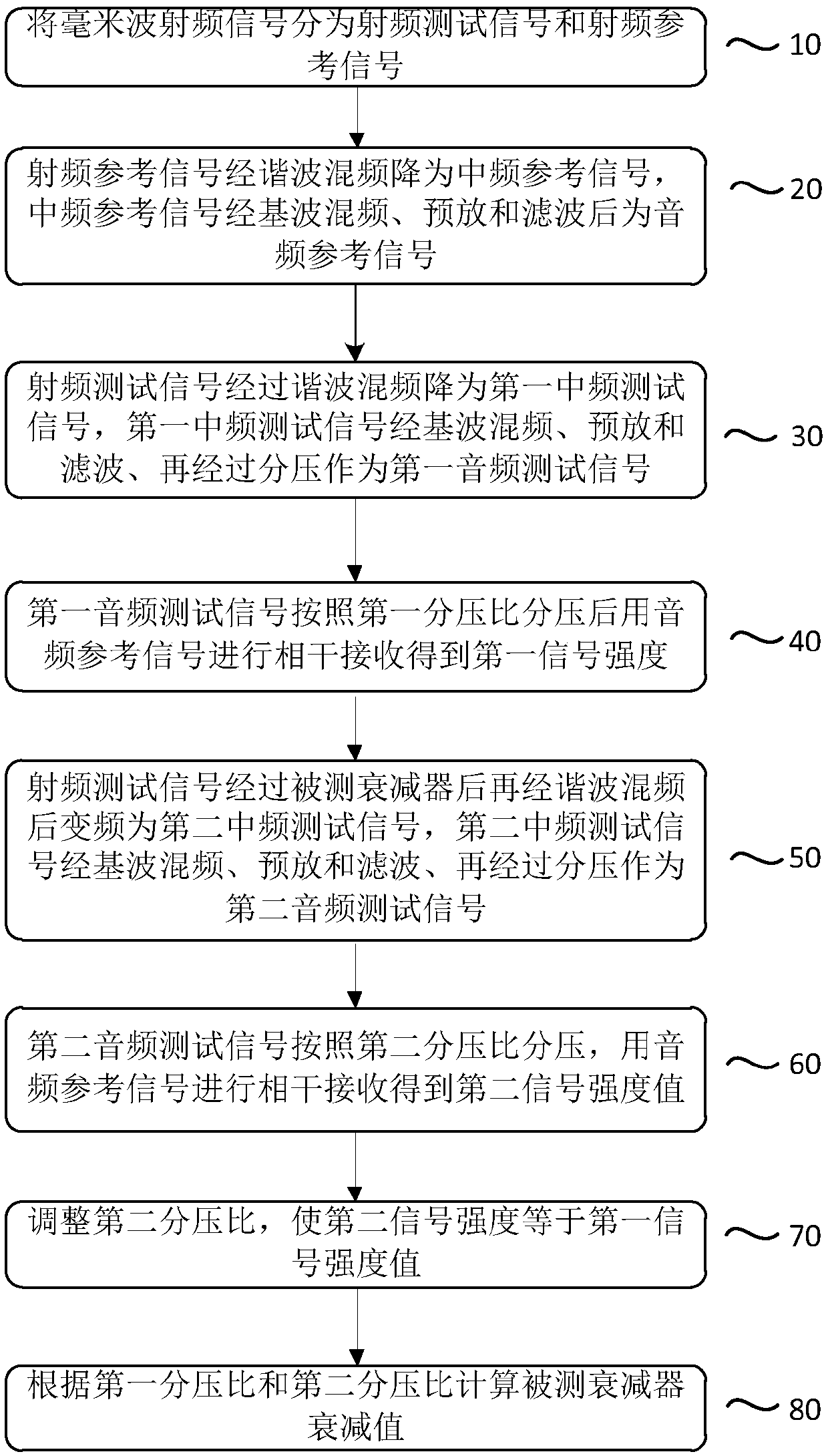
[0006] The present invention aims to solve the problem that the external reference frequency of the lock-in amplifier of the single-channel system is not synchronized with the frequency of the audio signal, the frequency jitter of the audio signal caused by the phase noise of the microwave signal generator in the single-channel system, the detection noise of the lock-in amplifier at the receiving end and the There are problems such as crosstalk between the two paths

Method used


Image

  • System and method of millimeter wave attenuation measurement
  • System and method of millimeter wave attenuation measurement
  • System and method of millimeter wave attenuation measurement

Examples


Embodiment Construction

[0050] In order to make the purpose, technical solution and advantages of the present application clearer, the technical solution of the present application will be clearly and completely described below in conjunction with specific embodiments of the present application and corresponding drawings. Apparently, the described embodiments are only some of the embodiments of the present application, rather than all the embodiments. Based on the embodiments in this application, all other embodiments obtained by persons of ordinary skill in the art without making creative efforts belong to the scope of protection of this application.

[0051] The present invention uses a test path and a reference path at the same time, converts the radio frequency signal on the test path into an audio signal and then divides the voltage and records the first division ratio before inserting the attenuator under test and the first division ratio after inserting the attenuator. Two voltage division rat...


PUM


Abstract

The application discloses a method of millimeter wave attenuation measurement and a system thereof. The method comprises: dividing a millimeter wave signal into a radio frequency test signal and a radio frequency reference signal; carrying out frequency conversion on the two radio frequency signals to form audio signals; and respectively carrying out voltage dividing on an audio test signal beforeand after insertion of the measured attenuator, using an audio reference signal for coherent receiving on the audio test signal to obtain two signal intensity values, enabling second signal intensityto be equal to first signal intensity, recording a first voltage dividing ratio and a second voltage dividing ratio, and calculating an attenuation value of the measured attenuator. The system of theinvention includes a radio frequency signal generator, a first directional coupler, an inductive voltage divider, a test unit, a reference unit, a lock-in amplifier and the measured attenuator. According to the method and the system, a two-channel signal measurement manner is employed, a measurement circuit is enabled to be stabler, the problem that external reference frequency and audio signal frequency of lock-in amplifiers of single-channel systems are not synchronized is solved, and the reference signal provided to the lock-in amplifier is very accurate.

Description

technical field [0001] The invention relates to the technical field of radio measurement, in particular to a millimeter wave attenuation measurement system and method. Background technique [0002] Electromagnetic waves in the frequency domain of 30-300 GHz (wavelength 1-10 mm) are usually called millimeter waves, which are located in the wavelength range where microwaves and far-infrared waves overlap, so they have the characteristics of both spectrums. Millimeter waves have numerous applications in areas such as communications, radar, remote sensing, and radio astronomy. Millimeter wave technology has made major breakthroughs in the development of transmitters, receivers, antennas, and millimeter wave devices, and millimeter wave radar has entered a new stage of various applications. [0003] The attenuation parameter is one of the basic parameters of radio metering, which characterizes the transmission characteristics of various transmission lines, electronic components,...

Claims


Application Information

Patent Timeline
Patent Type & Authority Applications(China)
IPC IPC(8): H04B17/318H04B17/309H04B17/00
CPCH04B17/0085H04B17/309H04B17/318
Inventor 徐宝利杨初刘杰李放
Owner BEIJING INST OF RADIO METROLOGY & MEASUREMENT
Why Eureka
Eureka Blog
Learn More