
Cutter head lifting structure and hay mower with same

A lifting structure and cutter head technology, which is applied to harvesters, agricultural machinery and tools, cutters, etc., can solve the problems of loose locking and increased costs, and achieve the effect of compact structure, convenient adjustment, and quick adjustment

Active Publication Date: 2019-04-16
ZHEJIANG SUNSEEKER IND CO LTD
View PDF9 Cites 4 Cited by
  • Summary
  • Abstract
  • Description
  • Claims
  • Application Information

AI Technical Summary

Problems solved by technology

[0003] But all there is the problem that locking is not firm in these thread adjusting structures, in order to solve the same problem but will not increase too much cost, the present invention designs a cutter head lifting mechanism, which can make the mower conveniently adjust the height, and the structure of the present invention is more Simple and cost-effective

Method used


Image

  • Cutter head lifting structure and hay mower with same
  • Cutter head lifting structure and hay mower with same
  • Cutter head lifting structure and hay mower with same

Examples


Embodiment 1

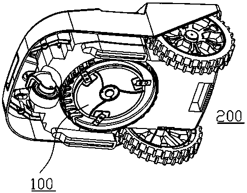
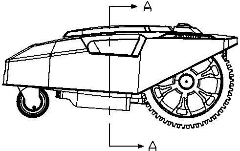
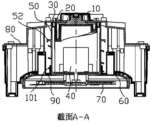
[0027] see Figure 1-7 , in an embodiment of the present invention, a cutter head lifting structure includes a cutting machine body 200; the cutting machine body 200 includes a base 90 and an upper shell 80 that are fixedly connected to each other, and the shell composed of the base 90 and the upper shell 80 is nested There is a cutterhead lifting assembly 100, and the cutterhead lifting assembly 100 includes a vertical moving part 1000 and a lifting spring 101; the vertical moving part 1000 includes a cutterhead 70, and the cutterhead 70 is connected to the output shaft of the cutterhead motor 40, and the cutterhead 70 outside cover is provided with cutter head cover 60, and cutter head cover 60 is protected to cutter head 70; Described cutter head cover 6 is fixedly connected with motor cover 50 by bolt, and motor cover 50 is set on the outside of cutter head motor 40, and cutter head The motor 40 is fixedly connected with the motor cover 50; the cutter head cover 60 is nest...

Embodiment 2

[0031] The difference between this embodiment and Embodiment 1 is that a lifting knob 10 is provided above the rotating block 20, and a block 23 is fixedly connected to the upper end surface of the rotating block 20, and the block 23 is clamped and fixed with the lifting knob 10. Realize the rotation of the rotating block 20, and then realize the lifting of the cutter head 70, and the adjustment is convenient and efficient.


PUM


Abstract

The invention discloses a cutter head lifting structure and a hay mower with the same. The hay mower comprises a cutter body; the cutter body comprises a base and an upper shell which are fixedly connected, a cutter head lifting assembly is nested into the shell composed of the base and the upper shell, and the cutter head lifting assembly comprises a vertical motion component and a lifting spring. By arranging a rotating block with the spiral ascending bottom face and a driven block with a driven block inner cavity, an elastic butting block is hinged to the outer wall of the rotating block, abutting protrusion grooves arranged in a spiral ascending mode are formed inside the driven block inner cavity, the vertical motion component abutting against a lifting spring is arranged, the heightof the cutter head is rapidly regulated through a lifting rotary knob, adjustment is convenient, and the structure is simple and compact.

Description

technical field [0001] The invention relates to the field of garden tools, in particular to a cutter head lifting structure and a lawnmower with the structure. Background technique [0002] Lawn mowers are common garden tools. With the continuous development of science and technology, highly intelligent automatic lawn mowers are becoming more and more common. Lawn mowers need to adjust the height of their cutter head according to different grass heights. For example, the publication number is CN201830660U The mowing cutter height adjustment mechanism and the corresponding lawn mower include a lead screw and a screw nut, the screw nut is fixed and rotatable, the lead screw is provided with a vertical guide mechanism, the interior of which is hollow, and a blade drive motor can be installed; and Publication No. CN107258207A lawn mower and sensor height control method, its technical solution is to include a rotating assembly, the rotating assembly can rotate, and the rotating a...

Claims


Application Information

Patent Timeline
IPC IPC(8): A01D34/74A01D34/82
CPCA01D34/74A01D34/82
Inventor 马妙武
Owner ZHEJIANG SUNSEEKER IND CO LTD
Learn More