Bundling machine for mechanically picking straw rods

A technology of baler and straw, which is applied in the field of baler for mechanized picking up straw, which can solve the problems of straw easy to fall, reduce the efficiency of picking up straw, and pick up unclean, so as to avoid the falling of straw, Improved stability and pickup efficiency

Active Publication Date: 2019-04-16
HUAIAN COLLEGE OF INFORMATION TECH
7 Cites 6 Cited by

AI-Extracted Technical Summary

Problems solved by technology

[0003] At present, the existing straw picking and bundling machines in the market rely on the rotating grass wheel to drive the grass pole to pick up the grass poles, and a torsion spring structure is sleeved at the joint between the grass pole and the grass wheel. The weight of the pole is light an...

Method used

Concretely improved, as shown in Figure 1: the end of described weeding bar 2 is arc-shaped curved shape, and described weeding bar 2 is connected with pressing grass roller 9, by making the end of weeding bar 2 The part is curved and curved, which is convenient to pick up the grass stalk on the one hand, and is convenient to cooperate with the grass pressing roller 9 on the other hand, so as to avoid the straw stalk from falling in the process of picking up.
Further improved, as shown in Figure 2: described fixed mount 8 is made up of side plate 11 and central plate 12, and described side plate 11 is fixedly connected at the two ends of central plate 12, and the bottom of described fixed mount 8 It is at the same height as the bottom of the grass retaining frame 3, and is fixedly connected with the central plate 12 in the middle of the side plate 11, so as to improve the structural strength of the fixed frame 8 and reduce the cost of manufacture simultaneously.
Further improved, as shown in Figure 3: the two ends of described grass pressing roller 9 are provided with the roller 15 that is rotationally connected, and described roller 15 is embedded in chute 14 and is connected with chute 14 rolling, by The two ends of the grass pressing roller 9 are provided with the roller 15 that is rotatably connected, which reduces the friction between the grass pressing roller 9 and the side plate 11, and facilitates the grass pressing roller 9 to rotate.
Please refer to Fig. 1-3 and the present invention provides a kind of technical scheme: a kind of baler of mechanization picking up grass bar, comprises weeding wheel 1, weeding bar 2, weed re...

Abstract

The invention discloses a bundling machine for mechanically picking up straw rods, which comprises a straw shifting wheel, straw shifting rods, straw blocking frames and an auxiliary straw pressing mechanism, wherein the surface of the straw shifting wheel is provided with mounting heads which are uniformly distributed annularly, and the surfaces of the mounting heads are provided with movably connected straw shifting rods; a torsion spring is arranged at the joint of the straw shifting rods and the mounting heads, one end of the torsion spring is fixedly connected with the straw shifting rods, the other end of the torsion spring is fixedly connected with the mounting heads, a rotating shaft is arranged in the center of the straw shifting wheel, the straw blocking frames is coaxially distributed at the edge of the straw shifting wheel in an arc shape, the auxiliary straw pressing mechanism is arranged on the right side of the straw blocking frame, the auxiliary straw pressing mechanismcomprises a fixing frame, straw pressing rollers and positioning sheets, the straw pressing rollers are uniformly distributed in the fixing frame and are connected with the fixing frame in a slidingway, and the positioning sheets are arranged between the straw pressing rollers. By the aid of the auxiliary straw pressing mechanism, the straws on the surface of the straw shifting rods is conveniently pressed and held, so that the straw shifting rods are prevented from falling off due to the elasticity of the torsion spring, and the stability and efficiency of straw picking are improved.

Application Domain

LoadersBaling

Technology Topic

Torsion springAgricultural engineering +1

Image

  • Bundling machine for mechanically picking straw rods
  • Bundling machine for mechanically picking straw rods
  • Bundling machine for mechanically picking straw rods

Examples

  • Experimental program(1)

Example Embodiment

[0016] The technical solutions in the embodiments of the present invention will be clearly and completely described below in conjunction with the drawings in the embodiments of the present invention.
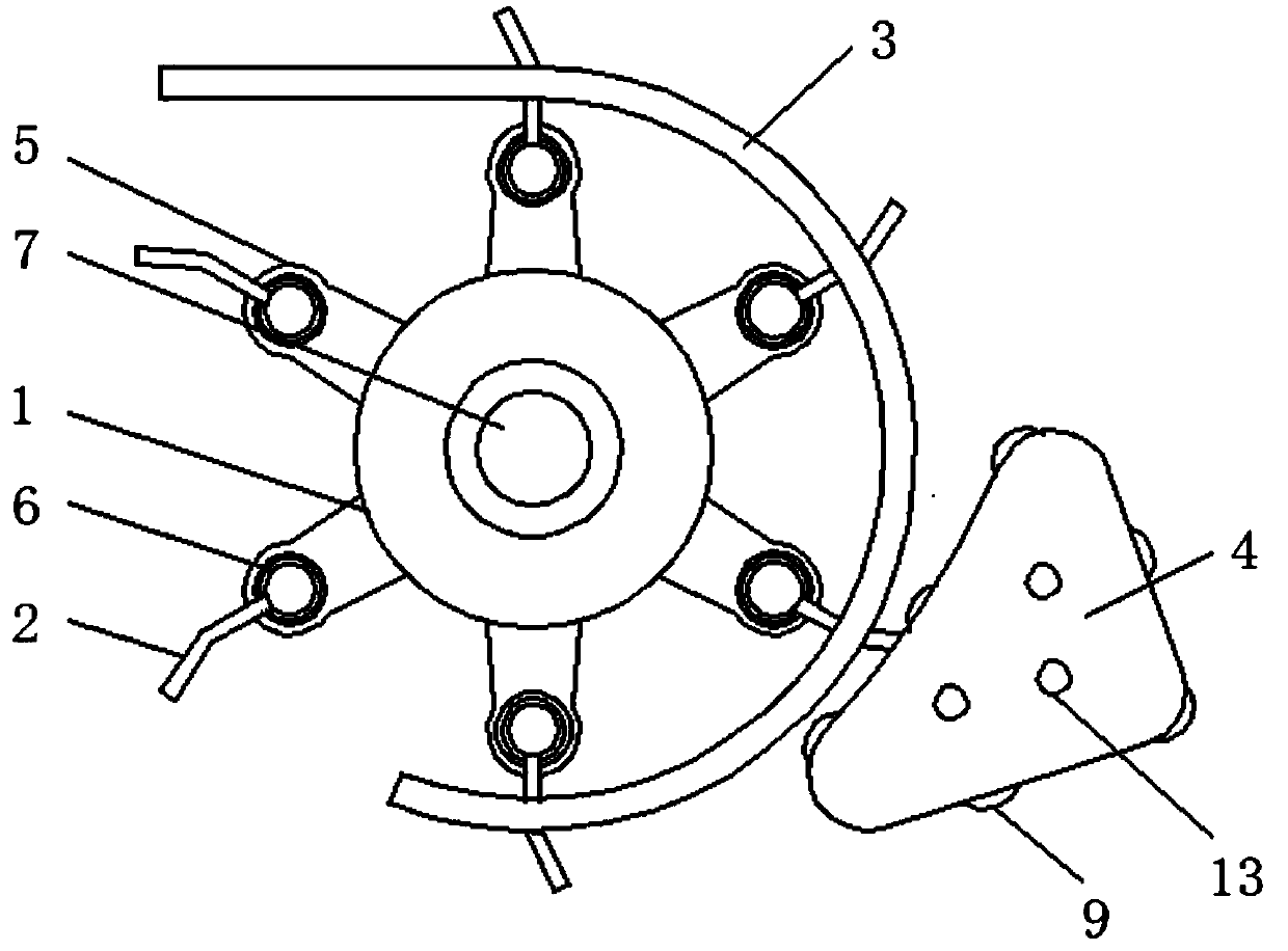
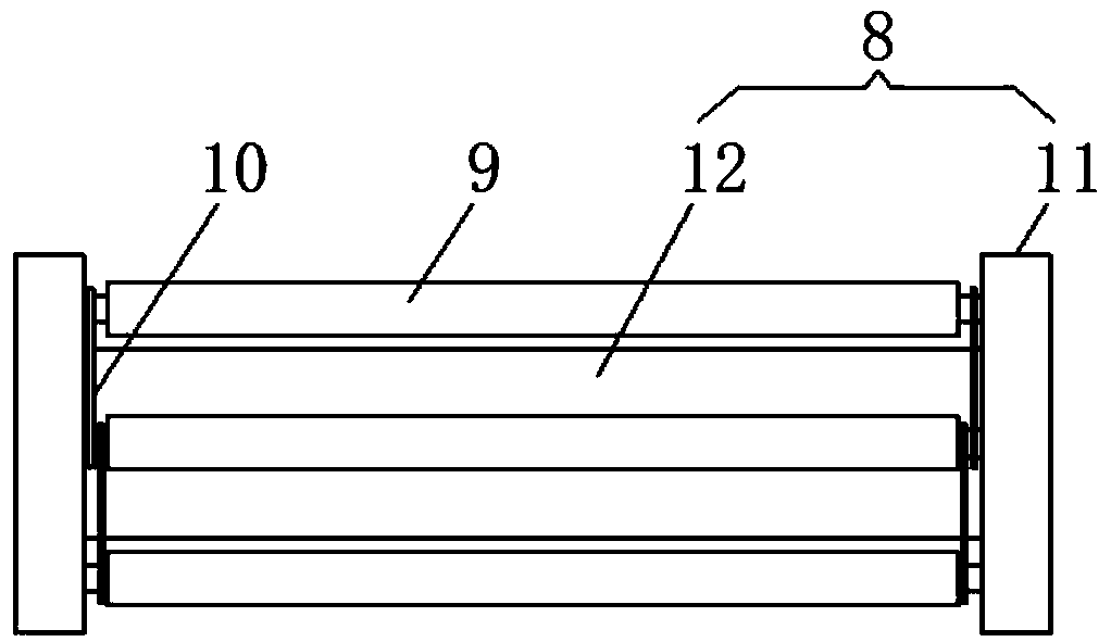
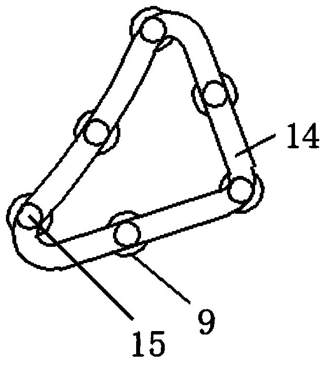
[0017] See Figure 1-3 The present invention provides a technical solution: a mechanized baling machine for picking up grass rods, comprising a grass turning wheel 1, a grass rod 2, a grass guard 3 and an auxiliary grass pressing mechanism 4. The surface of the grass turning wheel 1 is provided with There are mounting heads 5 evenly distributed in a ring shape. The surface of the mounting head 5 is provided with movably connected grass rods 2, and the connection between the grass rods 2 and the mounting heads 5 is provided with a torsion spring 6. One end of 6 is fixedly connected to the grass-pull rod 2 and the other end is fixedly connected to the mounting head 5. The center of the grass-pull wheel 1 is provided with a rotating shaft 7, and the grass-raising frame 3 is arc-shaped and coaxially distributed on the grass-pull wheel. At the edge of 1, the right side of the grass guard 3 is provided with an auxiliary grass pressing mechanism 4, the auxiliary grass pressing mechanism 4 includes a fixed frame 8, a grass roller 9 and a positioning sheet 10. The grass roller 9 is uniform Distributed in the fixing frame 8 and slidably connected to the fixing frame 8. The two ends of the grass pressing roller 9 are embedded in the fixing frame 8 and slidably connected to the fixing frame 8, and the grass pressing rollers 9 are arranged with each other. The blade 10 is provided with an auxiliary grass pressing mechanism 4, which facilitates pressing and holding of the grass rod on the surface of the grass rod 2, and prevents the grass rod from falling due to the elastic force of the torsion spring 6 when the grass rod 2 is separated from the ground. Improve the stability and efficiency of straw picking
[0018] Further improvements, such as figure 2 As shown: the fixing frame 8 is composed of a side plate 11 and a center plate 12. The side plates 11 are fixedly connected to both ends of the center plate 12, and the bottom of the fixing frame 8 is equal to the bottom of the grass guard 3, By fixing the central plate 12 in the middle of the side plate 11, the structural strength of the fixing frame 8 is improved, and the manufacturing cost is reduced.
[0019] Further improvements, such as figure 1 with 3 As shown: the outer surface of the side plate 11 is provided with a triangular distribution of fixing holes 13, and the inner surface of the side plate 11 is provided with a triangular chute 14, and the outer surface of the side plate 11 is provided with a triangular distribution The fixing hole 13 is convenient to connect the fixing frame 8 with the casing. By opening a triangular chute 14 on the inner surface of the side plate 11, it is convenient for the grass roller 9 to rotate in the fixing frame 8.
[0020] Further improvements, such as image 3 Shown: the two ends of the grass pressing roller 9 are provided with rotatably connected rollers 15 which are embedded in the chute 14 and are in rolling connection with the chute 14. The two ends of the grass roller 9 are provided with Rotating the connected roller 15 reduces the frictional force between the grass pressing roller 9 and the side plate 11 and facilitating the rotation of the grass pressing roller 9.
[0021] Specifically improved, such as figure 1 Shown: the end of the grass rod 2 is curved, and the grass rod 2 is in contact with the grass roller 9. By making the end of the grass rod 2 curved, one side is convenient The straw is picked up, and on the other hand, it is convenient to cooperate with the grass roller 9 to prevent the straw from falling during the picking process.
[0022] When the present invention is working, the tractor drives the baler to advance on the surface of the ground, and at the same time drives the rotating shaft 7 to drive the grass picker wheel 1 to rotate, the grass picker 2 rotates accordingly, and picks up the grass poles on the ground. When the grass pole 2 contacts the ground, the grass pole 2 rotates, and the grass pole 2 moves the grass pole to the surface of the grass pole 2. When the grass pole 2 leaves the ground, the grass pole 2 is affected by the torsion spring 6. The force produces sloshing, and at the same time it comes into contact with the grass roller 9 to prevent the grass rod from falling due to shaking. The grass rod 2 drives the grass roller 9 to move together, and the grass roller 9 gradually separates from the grass rod 2 with the movement. The rod 2 moves the grass rod upward along the grass retaining frame 3, which facilitates the baling operation of the grass rod by the baler.
[0023] The above shows and describes the basic principles and main features of the present invention and the advantages of the present invention. For those skilled in the art, it is obvious that the present invention is not limited to the details of the above exemplary embodiments, and without departing from the spirit or basics of the present invention. In the case of features, the present invention can be implemented in other specific forms. Therefore, from any point of view, the embodiments should be regarded as exemplary and non-limiting. The scope of the present invention is defined by the appended claims rather than the foregoing description, and therefore it is intended to fall within the claims. All changes within the meaning and scope of the equivalent elements of are included in the present invention. Any reference signs in the claims should not be regarded as limiting the claims involved.
[0024] In addition, it should be understood that although this specification is described in accordance with the implementation manners, not each implementation manner only includes an independent technical solution. This narration in the specification is only for clarity, and those skilled in the art should consider the specification as a whole The technical solutions in the embodiments can also be appropriately combined to form other implementations that can be understood by those skilled in the art.

PUM

no PUM

Description & Claims & Application Information

We can also present the details of the Description, Claims and Application information to help users get a comprehensive understanding of the technical details of the patent, such as background art, summary of invention, brief description of drawings, description of embodiments, and other original content. On the other hand, users can also determine the specific scope of protection of the technology through the list of claims; as well as understand the changes in the life cycle of the technology with the presentation of the patent timeline. Login to view more.
Why Eureka
Try Eureka