High-speed railcar ring-structure hydraulic damper piston rod assembling welding fixture

A technology for hydraulic shock absorbers and high-speed trains, used in manufacturing tools, welding equipment, auxiliary welding equipment, etc. The problem of difficulty in centering the connecting ring, etc., achieves the effect of high qualification rate and convenient assembly and welding

Pending Publication Date: 2019-04-16
ZHUHAI YECHENG RAIL TRANSPORTATION EQUIP TECH
View PDF0 Cites 3 Cited by
  • Summary
  • Abstract
  • Description
  • Claims
  • Application Information

AI Technical Summary

Problems solved by technology

The existing welding method first welds the connecting ring and the end cover, and it is difficult to align the end cover and the connecting ring when clamping. The existing machining method is used to process positioning holes and positioning pins on the connecting ring and the end cover, and then assemble after positioning butt welding
Due to the existence of secondary clamping and welding deformation, it is difficult to meet the shape and position tolerances of the connecting ring and end cap, and the pass rate is not high

Method used


Image

  • High-speed railcar ring-structure hydraulic damper piston rod assembling welding fixture
  • High-speed railcar ring-structure hydraulic damper piston rod assembling welding fixture
  • High-speed railcar ring-structure hydraulic damper piston rod assembling welding fixture

Examples


Embodiment Construction

[0023] In order to enable those skilled in the art to better understand the technical solutions of the present invention, the present invention will be further described in detail below in conjunction with specific examples. Please note that the embodiments described below are exemplary only for explaining the present invention, and should not be construed as limiting the present invention. If no specific technique or condition is indicated in the examples, it shall be carried out according to the technique or condition described in the literature in this field or according to the product specification. The reagents or instruments used were not indicated by the manufacturer, and they were all commercially available conventional products.

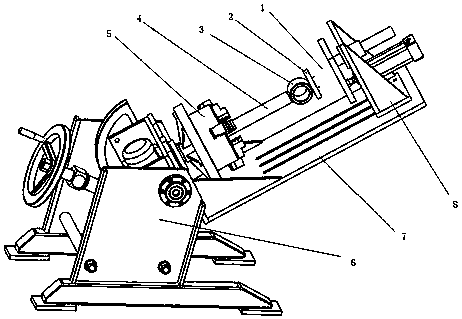
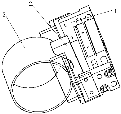
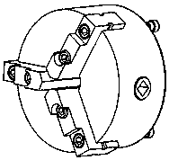
[0024] According to one aspect of the present invention, the present invention provides a ring structure oil pressure shock absorber piston rod assembly welding fixture for high-speed motor vehicles, figure 1 It is an overall structural dia...


PUM


Abstract

The invention relates to a high-speed railcar ring-structure hydraulic damper piston rod assembling welding fixture. The fixture comprises a large-bore finger air cylinder, a V-shaped positioning block, a single-axis servo positioner, a chuck, a fixture seat and a fixture installing seat, wherein the chuck and the fixture installing seat are arranged on the single-axis servo positioner so that orientation change of the chuck and the fixture installing seat can be achieved; the chuck is provided with gripper jaw so that a piston rod can be fixed; the fixture seat and the fixture installing seatare slidably connected so that the position of the fixture seat can be adjusted to adapt to the length of the piston rod; the fixture seat is provided with the large-bore finger air cylinder, the large-bore finger air cylinder is connected with the V-shaped positioning block, and the V-shaped positioning block is used for positioning a lifting ring; and after positioning of the piston rod and thelifting ring are completed, the single-axis servo positioner rotates, and welding is conducted. According to the high-speed railcar ring-structure hydraulic damper piston rod assembling welding fixture, the problem that the piston rod and a connection ring are difficult to position is solved, assembling welding is convenient, and the yield is high.

Description

technical field [0001] The invention belongs to the technical field of hydraulic shock absorbers for high-speed motor vehicles, and in particular relates to a welding jig for piston rod assembly of ring-structure hydraulic shock absorbers for high-speed motor vehicles. Background technique [0002] The high-speed EMU oil pressure shock absorber has high requirements on the shape and position tolerance of the connecting ring, end cover, and cylinder body. The parallelism is less than 0.2mm. The existing welding method first welds the connecting ring and the end cover, and it is difficult to align the end cover and the connecting ring when clamping. The existing machining method is used to process positioning holes and positioning pins on the connecting ring and the end cover, and then assemble after positioning Butt welding. Due to secondary clamping and welding deformation, the shape and position tolerances of the connecting ring and end cap are difficult to meet, and the ...

Claims


Application Information

Patent Timeline
Patent Type & Authority Applications(China)
IPC IPC(8): B23K37/04
CPCB23K37/0443
Inventor 杨贤群吴旭吴彤
Owner ZHUHAI YECHENG RAIL TRANSPORTATION EQUIP TECH
Why Eureka
Try Eureka