An energy-saving drilling device for mechanical parts

A technology for mechanical parts and drilling devices, which is applied in the field of energy-saving mechanical parts drilling devices, can solve the problems of wasting energy and cannot choose a drilling method, and achieves the effect of strong practicability.

Active Publication Date: 2021-09-24
宁波斯凯勒智能科技有限公司
View PDF6 Cites 0 Cited by
  • Summary
  • Abstract
  • Description
  • Claims
  • Application Information

AI Technical Summary

Problems solved by technology

However, this device simply drives the drilling motor up and down through the lifting device to realize the drilling operation, and the drilling method cannot be selected according to the weight of the parts, which wastes energy.

Method used


Image

  • An energy-saving drilling device for mechanical parts
  • An energy-saving drilling device for mechanical parts
  • An energy-saving drilling device for mechanical parts

Examples


Embodiment 1

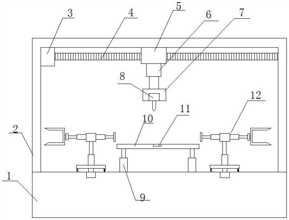
[0024] refer to figure 1 , in an embodiment of the present invention, an energy-saving drilling device for mechanical parts includes a workbench 1, a machine cover 2 is arranged on the upper side of the workbench 1, and a first motor is arranged on the upper left side of the inside of the machine cover 2 3. The output end of the first motor 3 is provided with a first threaded rod 4, the first threaded rod 4 is provided with a sliding seat 5, and the lower side of the sliding seat 5 is provided with a first telescopic device 6, so The lower end of the first telescopic device 6 is provided with a motor base 7, on which a drilling motor 8 is installed, and a second telescopic device 9 is arranged symmetrically in the middle of the upper side of the workbench 1. The upper end of the telescopic device 9 is provided with a part placement plate 10, the upper side of the part placement plate 10 is embedded with a pressure sensor 11, and the upper side of the workbench 1 is symmetrical...

Embodiment 2

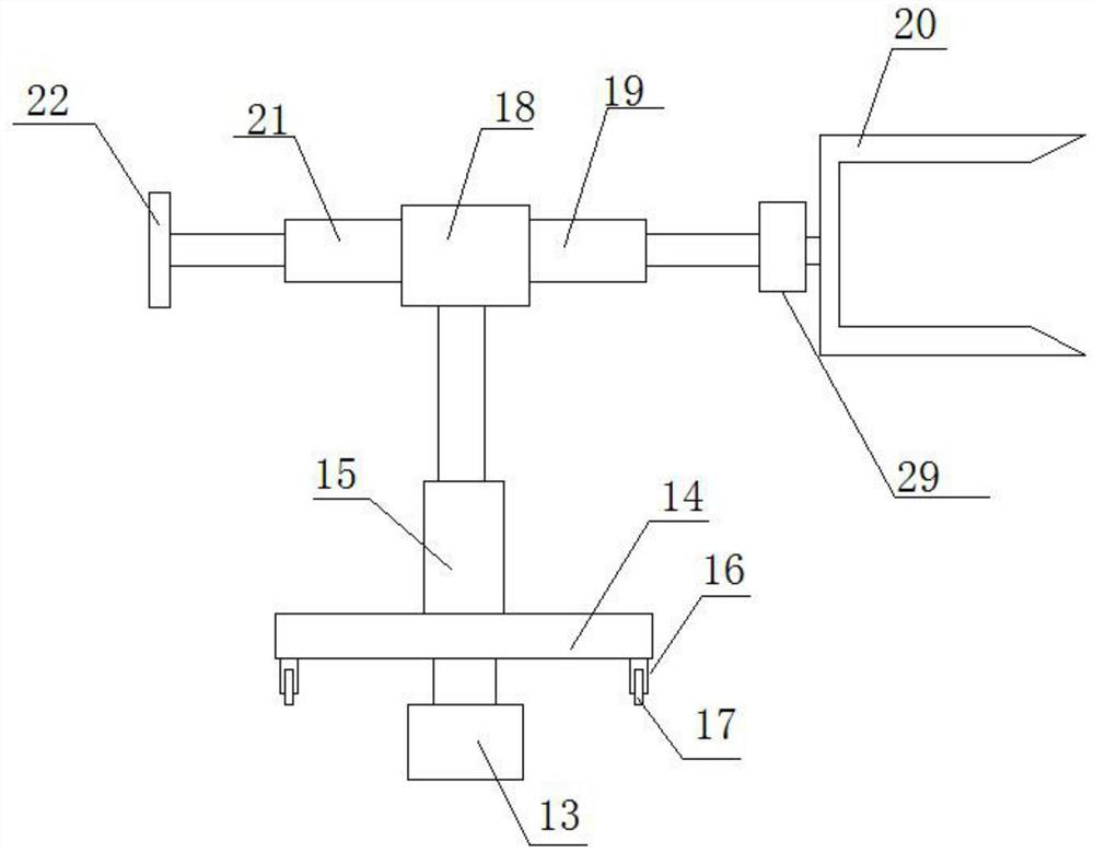
[0027] refer to figure 2 , the clamping mechanism 12 includes a second motor 13 embedded in the upper side of the workbench 1, the output end of the second motor 13 is provided with a rotating plate 14, and the lower side of the rotating plate 14 is symmetrically arranged with Rotary seat 16, the lower side of described rotary seat 16 is provided with runner 17, and the lower end of described runner 17 is arranged in conflict with workbench 1, and the middle of the upper side of described rotary plate 14 is provided with the 3rd telescoping device 15, so The upper end of the third telescopic device 15 is provided with a mounting seat 18, and the fourth telescopic device 21 and the fifth telescopic device 19 are symmetrically arranged on the mounting seat 18, and the outer end of the fourth telescopic device 21 is provided with a clip The holding plate 22 is provided with a fourth motor 29 at the outer end of the fifth telescopic device 19, and a clamping frame 20 is provided ...

Embodiment 3

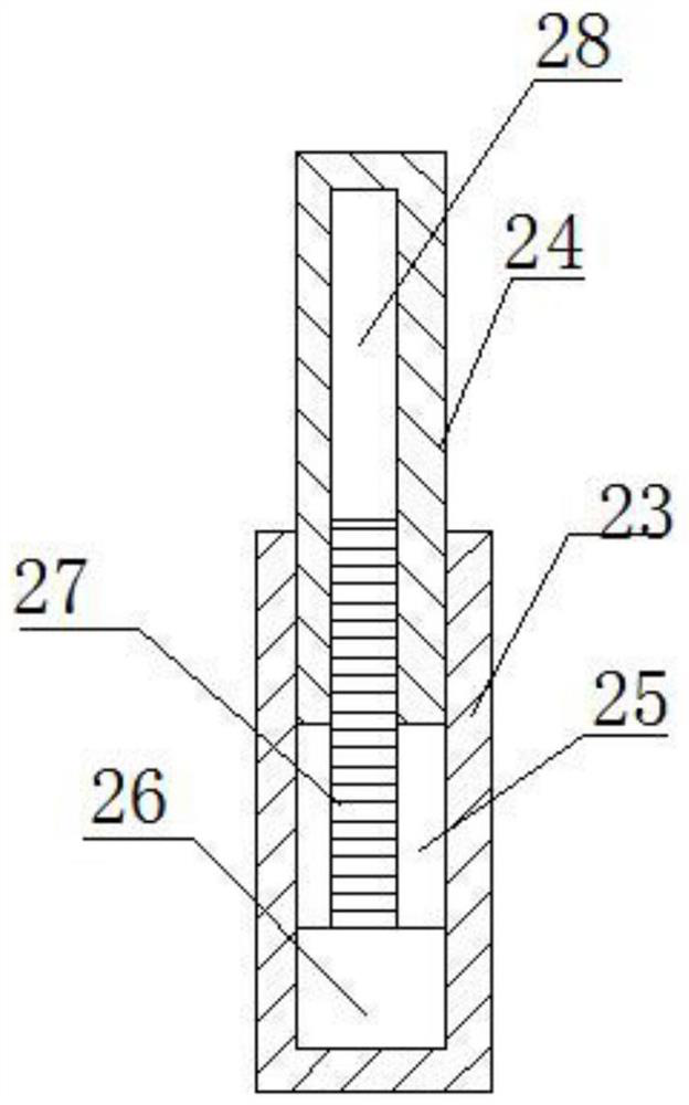
[0029] refer to image 3 , On the basis of the second embodiment, the first telescopic device 6 , the second telescopic device 9 , the third telescopic device 15 , the fourth telescopic device 21 and the fifth telescopic device 19 all include a support rod 23 and a telescopic rod 24 . The inside of the support rod 23 is provided with a telescopic chamber 25, the inside of the telescopic chamber 25 is provided with a third motor 26, the output end of the third motor 26 is provided with a second threaded rod 27, and the telescopic rod 24 A threaded cavity 28 is provided inside, the second threaded rod 27 is threadedly connected with the threaded cavity 28, and the support rod 23 and the telescopic rod 24 are both square structures. The forward and reverse rotation of the second threaded rod 27 can be driven by the third motor 26, thereby driving the telescopic rod 24 to expand and contract, realizing the first telescopic device 6, the second telescopic device 9, the third telesc...


PUM


Abstract

The invention relates to the technical field of drilling devices, in particular to an energy-saving drilling device for mechanical parts, which includes a workbench, a machine cover is arranged on the upper side of the workbench, a first motor is arranged on the upper left side of the inside of the machine cover, and the first motor The output end of the first threaded rod is provided with a first threaded rod, the first threaded rod is provided with a sliding seat, the lower side of the sliding seat is provided with a first telescopic device, the lower end of the first telescopic device is provided with a motor seat, and the motor seat is provided with A drilling motor is installed, and a second expansion device is symmetrically arranged in the middle of the upper side of the workbench. A part placement plate is arranged on the upper end of the second expansion device, and a pressure is embedded in the upper side of the part placement plate. For the sensor, the upper side of the workbench is symmetrically provided with clamping mechanisms located on the left and right sides of the part placement plate. The structural setting of the device can select the working mode according to the weight of the parts, and the work can be realized by using the minimum energy, which is energy-saving, environment-friendly and highly practical.

Description

technical field [0001] The invention relates to the technical field of drilling devices, in particular to an energy-saving drilling device for mechanical parts. Background technique [0002] Most of the mechanical parts have holes, so drilling the mechanical parts is a very important step in the processing of mechanical parts. During the drilling process, the contact between the mechanical parts and the drilling head will generate high-temperature sparks and a lot of dust. The high temperature of mechanical parts will affect the quality of drilling and reduce the qualified rate of mechanical parts processing. A large amount of dust floating into the air will affect the quality of air and endanger the health of workers. [0003] The Chinese patent application publication number is CN 108620620 A, which discloses a drilling device for mechanical parts. It can clamp mechanical parts of different shapes without changing different pressure plates, which can reduce time waste and...

Claims


Application Information

Patent Timeline
Patent Type & Authority Patents(China)
IPC IPC(8): B23Q17/20B23Q5/22B23Q5/28B23Q1/25
CPCB23Q1/25B23Q5/22B23Q5/28B23Q17/20B25H3/02
Inventor 乐东岳张国锐
Owner 宁波斯凯勒智能科技有限公司
Why Eureka
Try Eureka