A saw blade surface treatment device with a positioning structure

A technology of surface treatment device and positioning structure, which is applied to the device for coating liquid on the surface, metal processing equipment, coating, etc. It can solve the problems of not being able to realize the surface of the saw blade, increasing the processing cost, and applying antirust agent, etc., to achieve The effect of reducing the amount of labor, high functionality, and quick processing

Active Publication Date: 2020-11-20
ZHEJIANG NADIC CNC EQUIP CO LTD
View PDF7 Cites 0 Cited by
  • Summary
  • Abstract
  • Description
  • Claims
  • Application Information

AI Technical Summary

Problems solved by technology

[0003] 1. For the saw blades that need to be treated on a large number of surfaces in the workshop, the efficiency of manual grinding with sandpaper is low and the workload is large;
[0004] 2. For the treatment of the surface of the saw blade, it needs to be clamped to facilitate processing, but in the prior art, the size of the clamping structure of the saw blade is fixed, and the size of the saw blade corresponds to the clamping structure one by one, which increases the processing cost;
[0005] 3. The structure of the traditional saw blade surface treatment device is simple, only to polish the rust on the surface of the saw blade, and it is impossible to apply anti-rust agent on the surface of the saw blade

Method used


Image

  • A saw blade surface treatment device with a positioning structure
  • A saw blade surface treatment device with a positioning structure
  • A saw blade surface treatment device with a positioning structure

Examples


Embodiment Construction

[0024] The following will clearly and completely describe the technical solutions in the embodiments of the present invention with reference to the accompanying drawings in the embodiments of the present invention. Obviously, the described embodiments are only some, not all, embodiments of the present invention. Based on the embodiments of the present invention, all other embodiments obtained by persons of ordinary skill in the art without making creative efforts belong to the protection scope of the present invention.

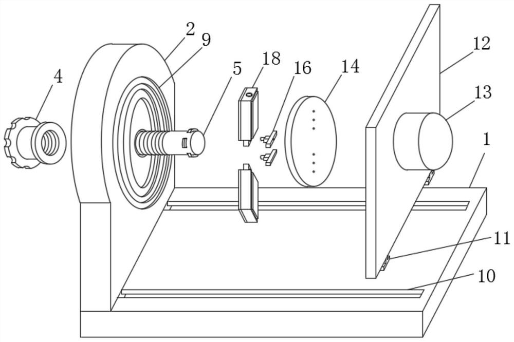
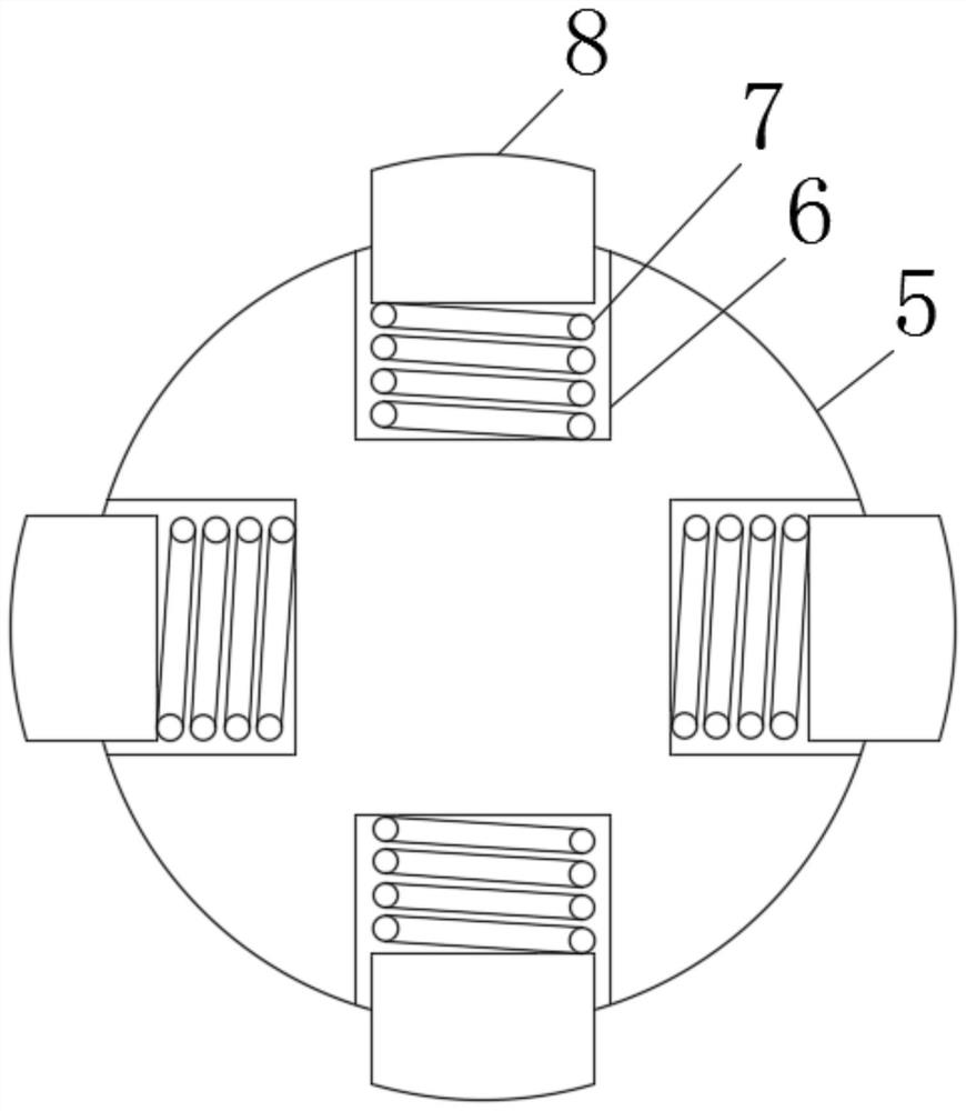
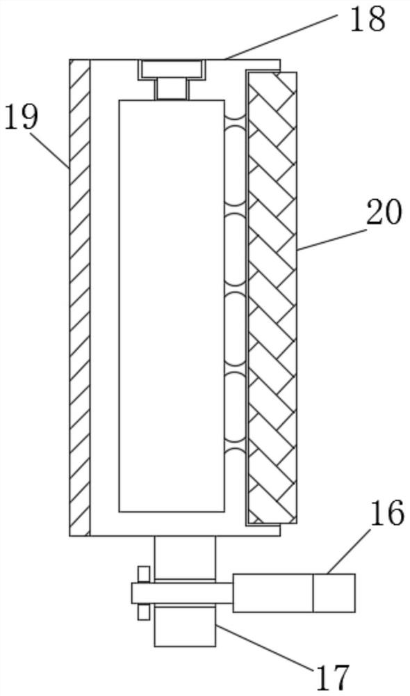
[0025] see Figure 1 to Figure 5 , the present invention provides a technical solution: a saw blade surface treatment device with a positioning structure, including a workbench 1, a vertical plate 2 and a movable plate 12, the vertical plate 2 is fixedly connected to the surface of the workbench 1, and the vertical plate A limit ring groove 3 is arranged on one side of the plate 2, the inside of the limit ring groove 3 is rotatably connected with an adjustment...


PUM


Abstract

The invention discloses a saw blade surface treatment device with a positioning structure.The saw blade surface treatment device with the positioning structure comprises a worktable, a vertical plate,and a movable plate, wherein the plate surface of the worktable is fixedly connected with the vertical plate, a limiting ring groove is formed in the plate surface of the vertical plate, the interiorof the limiting ringgroove is in rotary connection with an adjusting member, the interior of the adjusting member is inscrewed connection with a supporting rod, the supporting rod penetrates throughthe plate surface device of the vertical plate, a shrink groove is formed in the surface of the supporting rod, a clampingplate isconnected into the shrink groove in an inserted mode, a compression spring is fixedly connected between the clamping plate and the shrink groove, a saw blade placement groove is formed in the plate surface of the vertical plate,a guide sliding grooveis formed in the plate surface of the worktable, and a limiting sliding block is in sliding connection with the interior of the guide sliding groove.The saw blade surface treatment device is suitable for saw blades of different size,various types of saw blades are clamped bya clampingstructure, production input is reduced, andclamping operation of the clamping structure to the saw blades is easy and convenient.

Description

technical field [0001] The invention relates to the technical field of saw blade processing, in particular to a saw blade surface treatment device with a positioning structure. Background technique [0002] Saw blades are a general term for thin circular knives used to cut solid materials. Saw blades can be divided into: diamond saw blades for stone cutting; high-speed steel saw blades for metal ); used for cutting solid wood, furniture, wood-based panels, aluminum alloys, aluminum profiles, radiators, plastics, plastic steel, etc., because the saw blades are made of metal, the surface is prone to rust after long-term storage. Therefore, its surface needs to be treated, but it still has the following disadvantages in actual treatment: [0003] 1. For the saw blades that need to be treated on a large number of surfaces in the workshop, the efficiency of manual grinding with sandpaper is low and the workload is large; [0004] 2. For the treatment of the surface of the saw b...

Claims


Application Information

Patent Timeline
Patent Type & Authority Patents(China)
IPC IPC(8): B24B27/033B24B41/06B05C1/06
CPCB05C1/06B24B27/033B24B41/06
Inventor 崔甜卉
Owner ZHEJIANG NADIC CNC EQUIP CO LTD
Why Eureka
Try Eureka