Tool structure suitable for intelligent welding of vehicle trim parts

An intelligent technology for automotive trims, applied in the field of tooling structure for intelligent welding of automotive trims, can solve problems such as inconvenient adjustment, poor welding quality of automotive trims, and small application range, etc., to enhance welding quality, improve welding efficiency, The effect of improving welding quality

Inactive Publication Date: 2019-04-16
WUHU XINBAO ULTRASONIC EQUIP
View PDF10 Cites 2 Cited by
  • Summary
  • Abstract
  • Description
  • Claims
  • Application Information

AI Technical Summary

Problems solved by technology

[0003] The purpose of the present invention is to provide a device with a reasonable structure design, good stability during the welding process of automobile trims, and an High efficiency, wide application range, good welding quality of automotive trims Suitable for tooling structure of intelligent welding of automotive trims

Method used


Image

  • Tool structure suitable for intelligent welding of vehicle trim parts
  • Tool structure suitable for intelligent welding of vehicle trim parts
  • Tool structure suitable for intelligent welding of vehicle trim parts

Examples


Embodiment 1

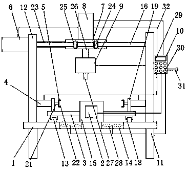
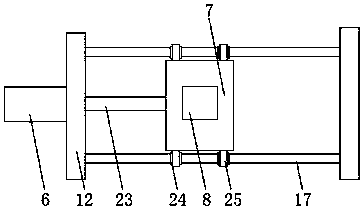
[0021] as attached Figure 1-3 As shown, a tooling structure suitable for intelligent welding of automotive trims, including console 1, hydraulic cylinder 1 2, load plate 3, hydraulic cylinder 2 4, fastening block 5, hydraulic cylinder 3 6, moving block 7, hydraulic Cylinder 4 8, welder 9 and controller 10 are characterized in that: described console 1 is arranged on the support 11, and is provided with vertical plate 12, slide rail 13, air outlet 14, positioning on console 1 Plate 15, a slide bar 16 is arranged between the vertical plate 12 and the vertical plate 12, the hydraulic cylinder one 2 is arranged on the positioning plate 15, and a piston rod one 17 is arranged on the hydraulic cylinder one 2, so The bearing plate 3 is provided with a slide block 18 and a fixed plate 19, and the slide block 18 is arranged on the slide rail 13, and the hydraulic cylinder two 4 is arranged on the fixed plate 19, and the hydraulic cylinder two 4 Piston rod 2 21 is arranged on the top,...

Embodiment 2

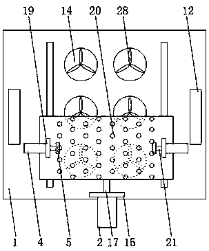
[0029] as attached Figure 4-5 As shown, a tooling structure suitable for intelligent welding of automotive trims, including console 1, hydraulic cylinder 1 2, load plate 3, hydraulic cylinder 2 4, fastening block 5, hydraulic cylinder 3 6, moving block 7, hydraulic Cylinder 4 8, welder 9 and controller 10 are characterized in that: described console 1 is arranged on the support 11, and is provided with vertical plate 12, slide rail 13, air outlet 14, positioning on console 1 Plate 15, a slide bar 16 is arranged between the vertical plate 12 and the vertical plate 12, the hydraulic cylinder one 2 is arranged on the positioning plate 15, and a piston rod one 17 is arranged on the hydraulic cylinder one 2, so The bearing plate 3 is provided with a slide block 18 and a fixed plate 19, and the slide block 18 is arranged on the slide rail 13, and the hydraulic cylinder two 4 is arranged on the fixed plate 19, and the hydraulic cylinder two 4 Piston rod 2 21 is arranged on the top,...


PUM


Abstract

The invention discloses a tool structure suitable for intelligent welding of vehicle trim parts. The tool structure comprises a console, a first hydraulic cylinder, a bearing plate, a second hydrauliccylinder, a fastening block, a third hydraulic cylinder, a movable block, a fourth hydraulic cylinder, a welder and a controller. The tool structure is characterized in that the console is arranged on a bracket; a slide rod is arranged between a vertical plate and a vertical plate; the first hydraulic cylinder is arranged on a positioning plate; a first slide block and a fixed plate are arrangedon the bearing plate; the second hydraulic cylinder is arranged on the fixed plate; the fastening block is arranged on a second piston rod; and the third hydraulic cylinder is arranged on the verticalplate. The direction of the first hydraulic cylinder and a first piston rod pushing the bearing plate is perpendicular to the direction of the third hydraulic cylinder and a third piston rod pushingthe movable block, so that the vehicle trim parts and the welder can relatively move in the welding process, the vehicle trim parts can be welded in different positions, the welding quality of the vehicle trim parts is improved, and the application range of the welding tool structure is widened.

Description

technical field [0001] The invention relates to the technical field of automotive trim welding, in particular to a tooling structure suitable for intelligent welding of automotive trim. Background technique [0002] The welding machine for automotive interior parts mainly welds plastic parts through a welding head controlled by temperature. When welding, the welding tip is placed between two plastic parts, and when the workpiece is pressed against the welding tip, the plastic begins to melt. After a preset heating time has elapsed, the plastic on the surface of the workpiece will reach a certain degree of melting. At this time, the workpiece is separated to both sides, the welding head is moved away, and then the two workpieces are fused together. When a certain welding time and welding are reached After the depth, the whole welding process is completed. For example, the patent application number 201621018969.2 discloses the welding tool for the manufacture of automotive i...

Claims


Application Information

Patent Timeline
Patent Type & Authority Applications(China)
IPC IPC(8): B29C65/02B29C65/78B29L31/30
CPCB29C65/02B29C65/7841B29L2031/3005
Inventor 潘保平
Owner WUHU XINBAO ULTRASONIC EQUIP
Why Eureka
Try Eureka