Semi-trailer tractor working platform device

A working platform and tractor technology, which is applied in the directions of vehicle components, transportation and packaging, and the arrangement of pedals or ladders, can solve the problems of low rigidity and difficult assembly, and achieve the effects of easy assembly, easy operation and high reliability

Pending Publication Date: 2019-04-16
DONGFENG COMML VEHICLE CO LTD
View PDF6 Cites 0 Cited by
  • Summary
  • Abstract
  • Description
  • Claims
  • Application Information

AI Technical Summary

Problems solved by technology

[0007] The purpose of the present invention is to overcome the defects and problems of low rigidity and difficult assembly in the prior art, and provide a semi-trailer tractor working platform device with high rigidity and easy assembly

Method used


Image

  • Semi-trailer tractor working platform device
  • Semi-trailer tractor working platform device
  • Semi-trailer tractor working platform device

Examples


Embodiment 1

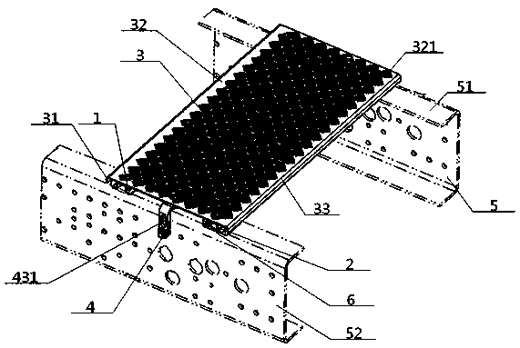
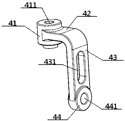
[0043] see Figure 1 to Figure 3 , a working platform device for a semi-trailer tractor, comprising a platform plate 3, a connecting bracket 4, and a left reinforcing plate 1 and a right reinforcing plate 2 parallel to each other, the top surfaces of the left reinforcing plate 1 and the right reinforcing plate 2 are all connected to each other. The bottom surface of the platform deck 3 is connected, the bottom surfaces of the left reinforcing plate 1 and the right reinforcing plate 2 are in contact with the upper wing surface 51 of the longitudinal beam 5, and the intersection of the left reinforcing plate 1 and the platform deck 3 is close to the platform deck 3 The left side of the right reinforcement board 2 and the junction of the platform deck 3 are arranged near the right side of the platform deck 3, and the connecting bracket 4 is located between the left reinforcement board 1 and the right reinforcement board 2. Preferably, the cross-sections of the left reinforcing pl...

Embodiment 2

[0045] Basic content is the same as embodiment 1, the difference is:

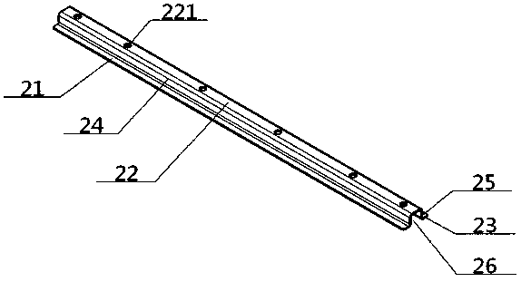
[0046] When the cross-sections of the left reinforcement board 1 and the right reinforcement board 2 are several fonts, they all include a left bottom plane 21, a mid-high plane 22 and a right bottom plane 23, and the mid-high plane 22 is higher than the left bottom plane 21 and the right bottom plane. The plane 23 is set, the inner end of the left bottom plane 21 is connected to one end of the middle height plane 22 through the left vertical board surface 24, and the other end of the middle height plane 22 is connected to the inner end of the right bottom plane 23 through the right vertical board plane 25 , and the left vertical plate surface 24, the middle high plane 22, and the right vertical plate surface 25 are clamped into a downwardly opening reinforcing cavity 26; the angle between the left bottom plane 21 and the left vertical plate surface 24, and the right The angle between the bottom plane 23 an...

Embodiment 3

[0048] Basic content is the same as embodiment 1, the difference is:

[0049] The bottom surfaces of the left reinforcing plate 1 and the right reinforcing plate 2 are bonded to the upper wing surface 51 of the longitudinal beam 5 through the shock-absorbing rubber 6 . Alternatively, shock-absorbing rubber 6 is filled in the reinforcement cavity 26 directly above the upper airfoil 51 .


PUM


Abstract

A semi-trailer tractor working platform device comprises a platform plate, connecting brackets, a left reinforcing plate and a right reinforcing plate. The top surfaces of the left and right reinforcing plates are connected with the bottom surface of the platform plate, the bottom surfaces of the left and right reinforcing plates are in contact with the upper wing surfaces of longitudinal beams, the connecting brackets are located between the left and right reinforcing plates, the cross sections of the left reinforcing plate and the right reinforcing plate are both in the shape of a Chinese character 'ji' or a groove shape or a rectangular shape or an I shape, the bottom surfaces of the left reinforcing plate and the right reinforcing plate can fit the upper wing surfaces of the longitudinal beams through damping rubber, each connecting bracket comprises an upper connecting head, a transverse connecting plate, a vertical connecting plate and a lower connecting head, and anti-slip patterns can be arranged on the top surface of the platform plate. The semi-trailer tractor working platform device is large in rigidity, easy to assemble, high in durability, reliability and adjustabilityand low in cost.

Description

technical field [0001] The invention relates to a working platform, which belongs to the field of truck parts, in particular to a working platform device for a semi-trailer tractor, which is particularly suitable for increasing rigidity and reducing assembly difficulty. Background technique [0002] In order to facilitate the connection of lines and pipelines between the tractor and the trailer, the area behind the cab and above the gearbox of the existing semi-trailer tractor is covered with a working platform device. This device often includes a workbench platen, and is connected with the left and right longitudinal beams through connecting brackets. [0003] The authorized announcement number is CN201961400U, and the authorized announcement date is September 7, 2011. The utility model patent discloses a vehicle workbench, including a workbench, a metal support and a connecting bracket, wherein the workbench is molded by SMC sheet plastic , the top is provided with anti-s...

Claims


Application Information

Patent Timeline
Patent Type & Authority Applications(China)
IPC IPC(8): B60R3/00
CPCB60R3/005
Inventor 王君刚段俊英薛鹏飞熊桦
Owner DONGFENG COMML VEHICLE CO LTD
Why Eureka
Try Eureka