Plastering device for buildings

A technology for construction and plastering boards, which is applied in the direction of construction and building construction, and can solve the problems of easy blockage of pipelines, high requirements for feeding pumps, and heavy weight of mortar boxes, so as to avoid large bending and reliably transport mortar , the effect of ingenious structure

Inactive Publication Date: 2019-04-16
江苏中鑫项目管理有限公司 +1
View PDF6 Cites 4 Cited by
  • Summary
  • Abstract
  • Description
  • Claims
  • Application Information

AI Technical Summary

Problems solved by technology

[0004] In the first structure, the weight of the mortar box is heavy, and the energy consumption is high when lifting, and the lifting seat with heavy load has high requirements on the reliability of the structure; in the second structure, because the lifting seat will move up and down frequently, and the movement range is relat...

Method used


Image

  • Plastering device for buildings
  • Plastering device for buildings
  • Plastering device for buildings

Examples


Embodiment 1

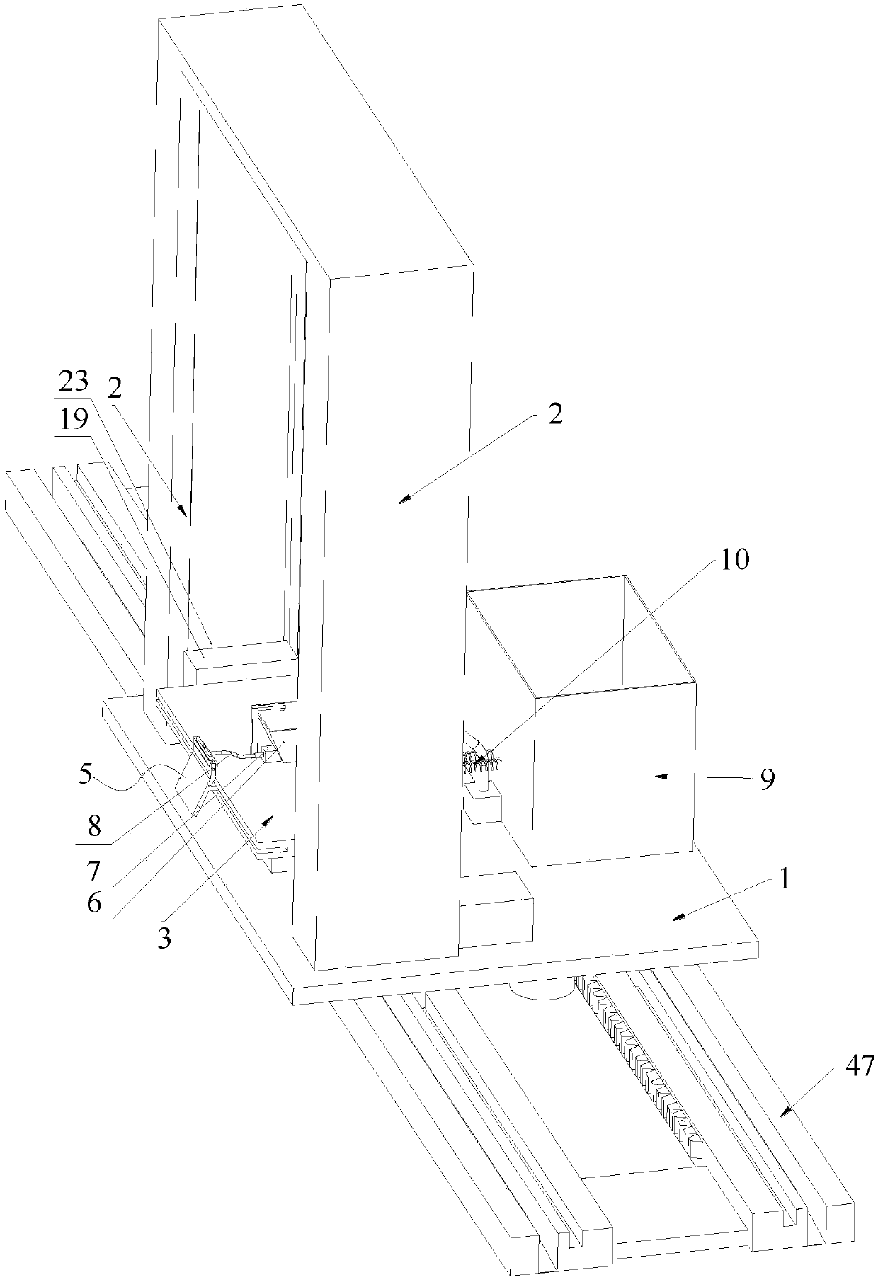
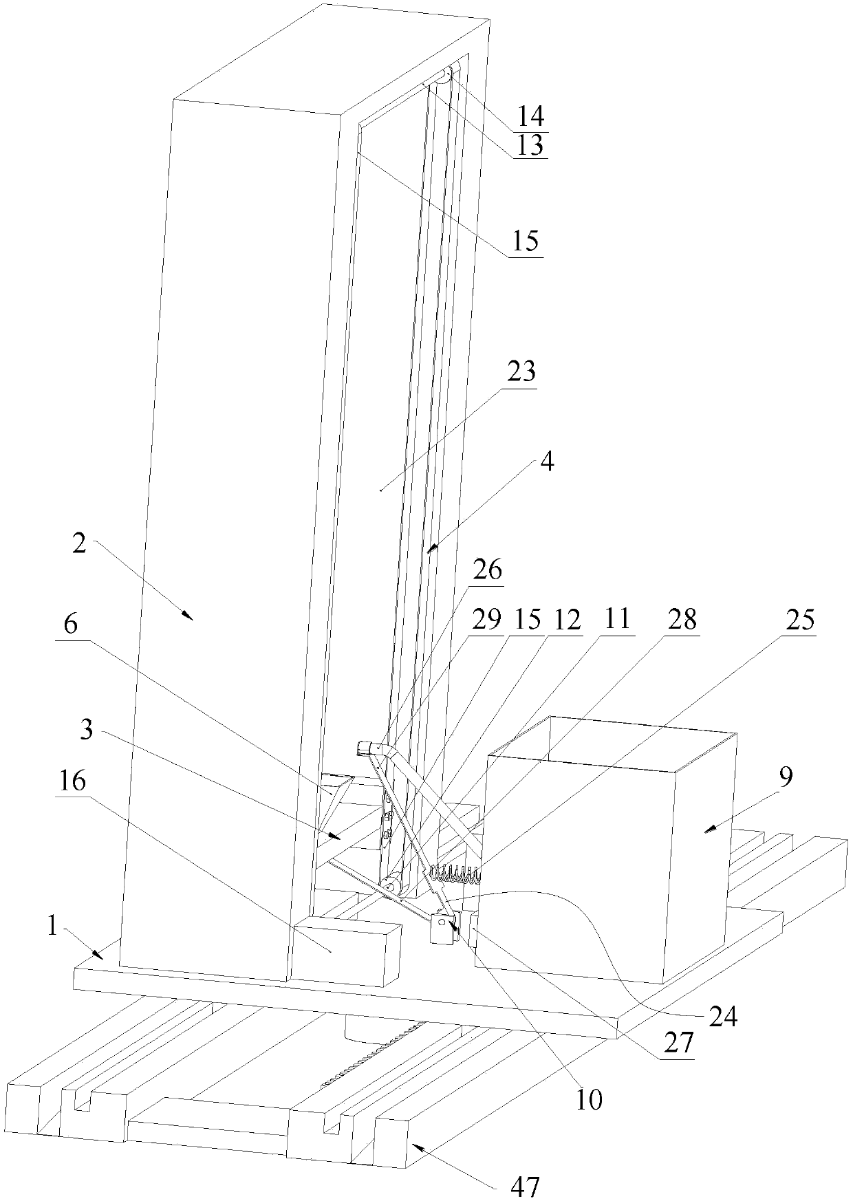
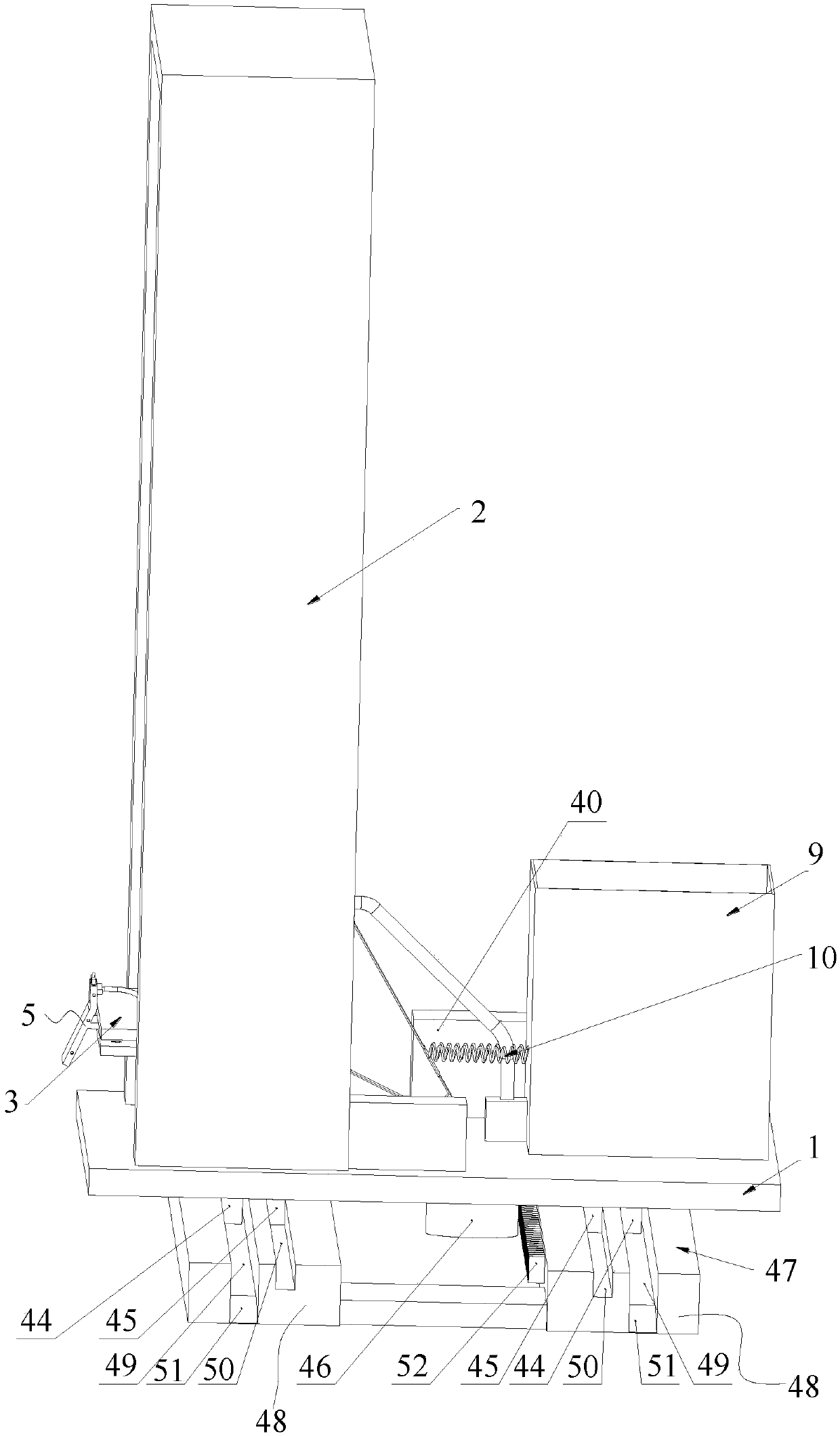
[0070] Such as figure 1 , 2 Shown in and 3, a kind of plastering device for building, comprises:

[0071] base1;

[0072] Two columns 2 are fixed on the base 1;

[0073] The lifting seat 3 is movable between the two columns 2 and can move up and down reciprocatingly;

[0074] The lifting mechanism 4 is used to drive the lifting seat 3 to reciprocate up and down;

[0075] Plastering board 5 is installed on the lifting seat 3;

[0076] The storage funnel 6 is fixed on the lifting seat 3 and is used to store the mortar;

[0077] The feed pump 7 is arranged at the lower part of the storage funnel 6, and is used to transport the mortar in the storage funnel 6 to the plastering board 5 through the first pipeline 8, so that the mortar is sprayed to the wall;

[0078] The mortar box 9 is fixed on the base 1;

[0079] The feeding mechanism 10 is used to transport the mortar in the mortar box 9 to the storage funnel 6 when the lifting base 3 is at the lowest position.

[0080] I...

Embodiment 2

[0112] Such as Figure 13 and 14As shown, the difference between this embodiment and Embodiment 1 is that there are multiple plastering boards 5 in this embodiment, and connecting pieces 57 are also included. , wherein the connecting column 58 of one plastering board 5 is inserted into the connecting groove 59 of the other plastering board 5, and the two ends of the connecting piece 57 are respectively fixed with two adjacent second threaded holes 54 by screws;

[0113] In the present embodiment, the quantity of the feeding pump 7 is the same as that of the plastering board 5, and the feeding pump 7 is used to convey mortar to the corresponding plastering board 5, and the storage funnel 6 has a feeding pump 7 that is connected to the storage funnel. Material funnel 6 cooperates. During actual use, when there are multiple storage funnels 6, the storage funnels 6 and the feeding pumps are matched one by one.

[0114] Through the cooperation of the horizontal groove 53, the ho...


PUM


Abstract

The invention discloses a plastering device for buildings, which comprises a base; two upright posts; a lifting seat movably arranged between the two upright posts; a lifting mechanism used for driving the lifting seat to reciprocate up and down; a plastering plate arranged on the lifting seat; a storage hopper fixed on the lifting seat; a material conveying pump arranged at the lower part of thematerial storage hopper and used for conveying the mortar in the material storage hopper to a plastering plate through a first pipeline; a mortar box fixed on the base; a feeding mechanism used for conveying the mortar in the mortar box into the storage hopper when the lifting seat is in the lowest position. The storage hopper is used for storing a small amount of mortar, and the mortar box is used for storing a large amount of mortar, so that the weight of the lifting seat can be effectively reduced; when the lifting seat is positioned at the lowest position, the mortar in the mortar box is conveyed to the storage hopper through the feeding mechanism, so that the requirement of the structure on a pump is low, the problem of frequent and large-scale bending of pipelines is avoided, and thereliable mortar conveying can be ensured.

Description

technical field [0001] The invention relates to the technical field of construction equipment, in particular to a construction plastering device. Background technique [0002] Most of the plastering of interior and exterior walls in the construction industry is done manually, which is inefficient and slow, and takes up a lot of time and labor. With the development of the aging of Chinese society, the decline of the labor force will exacerbate the current "labor shortage" problem, which will greatly affect the construction and cause the construction cost to rise. [0003] In view of the above problems, a plastering device has appeared in the prior art, and the wall is plastered by the plastering device, thereby reducing the labor intensity. There are two main types of existing plastering devices. The first is that the mortar box is directly set on the lifting base, and then the mortar in the mortar box is plastered on the wall through the plastering board through the slope; ...

Claims


Application Information

Patent Timeline
IPC IPC(8): E04F21/08E04F21/12
CPCE04F21/08E04F21/12
Inventor 邱林吴书安
Owner 江苏中鑫项目管理有限公司
Why Eureka
Try Eureka