
Liquefied gas cylinder valve protection device

A protection device, a technology for liquefied gas cylinders, applied in gas/liquid distribution and storage, fluid processing, container discharge methods, etc. Easy to operate effect

Inactive Publication Date: 2019-04-16
YANGZHOU ANYI VALVE
View PDF1 Cites 0 Cited by
  • Summary
  • Abstract
  • Description
  • Claims
  • Application Information

AI Technical Summary

Problems solved by technology

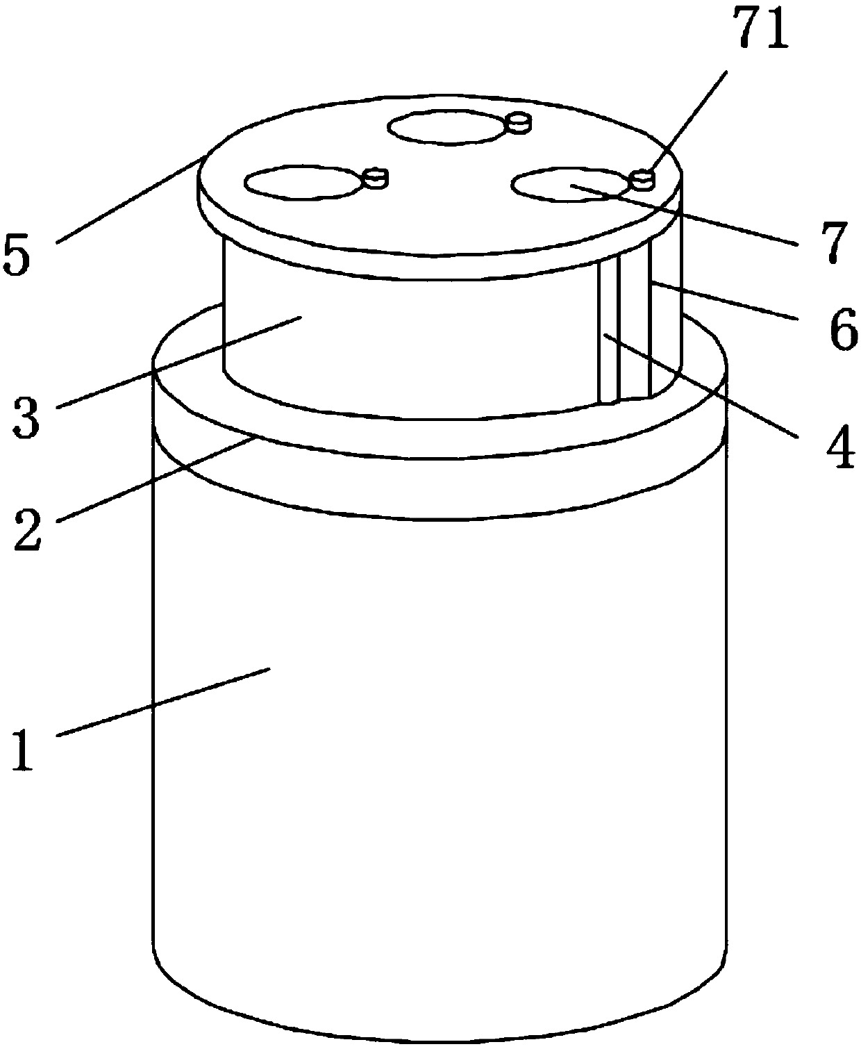
[0002] The gas cylinder valve refers to the valve installed on the gas cylinder to control the on-off and flow of gas. Usually, the gas cylinder valve needs to be protected. Therefore, a protection device is required, but the existing protection device is simple in structure and does not Compared with the Chinese patent CN201520440614.1 vehicle liquefied natural gas cylinder valve protection device, its advantage is that the protection ring adopts a stainless steel structure to ensure the safety strength, and the rest of the components are integrally formed with PC materials that meet the strength. Low cost, good appearance and light weight. The hand wheel structure in this system can be adjusted and locked freely, which is convenient for operation and maintenance. In this system, transparent materials are used to protect the valves and instruments on the protection ring, and it is easy to observe However, it is not convenient for the user to install and disassemble the connection frame, and it is not possible to store the hand wheel cover well. When the user adjusts the valve body, the hand wheel cover is easy to affect the user's control of the valve body. The adjustment of the cylinder valve is not convenient for the user to operate

Method used


Image

  • Liquefied gas cylinder valve protection device
  • Liquefied gas cylinder valve protection device
  • Liquefied gas cylinder valve protection device

Examples


Embodiment Construction

[0024] The following will clearly and completely describe the technical solutions in the embodiments of the present invention with reference to the accompanying drawings in the embodiments of the present invention. Obviously, the described embodiments are only some, not all, embodiments of the present invention. Based on the embodiments of the present invention, all other embodiments obtained by persons of ordinary skill in the art without making creative efforts belong to the protection scope of the present invention.

[0025] In the description of the present invention, it should be noted that the terms "upper", "lower", "inner", "outer", "front end", "rear end", "both ends", "one end", "another end" The orientation or positional relationship indicated by etc. is based on the orientation or positional relationship shown in the drawings, and is only for the convenience of describing the present invention and simplifying the description, rather than indicating or implying that ...


PUM


Abstract

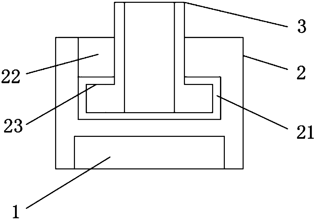
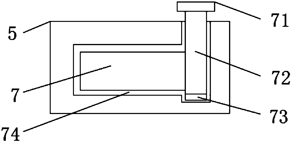
The invention discloses a liquefied gas cylinder valve protection device, comprising a gas cylinder, wherein the outer surface of an upper end of the gas cylinder is movably connected with a connection frame; the upper end of the connection frame is movably connected with a protection ring; the outer surface of one side of the protection ring is fixedly connected with a hinge; a position, close tothe hinge, of the outer surface of one side of the protection ring is fixedly connected to a protection cover; the outer surface of the upper end of the protection ring is fixedly connected with a top plate; the upper end of the top plate is movably connected with a handle; the inner side of the top plate is movably connected with a hand wheel cover; the inner side of the connection frame is provided with an annular groove; and a position, near the upper end, of the inner side of the connection frame is provided with a limit groove. The invention has a series of structures to make the devicehave better storability during use, can facilitate the installation and disassembly of the connection frame by the user, and can better accommodate the hand wheel cover to avoid external influence tothe adjustment of a gas cylinder valve by the user, thus being convenient for the user to operate.

Description

technical field [0001] The invention relates to the technical field of protection devices, in particular to a valve protection device for liquefied gas cylinders. Background technique [0002] The gas cylinder valve refers to the valve installed on the gas cylinder to control the on-off and flow of gas. Usually, the gas cylinder valve needs to be protected. Therefore, a protection device is required, but the existing protection device is simple in structure and does not Compared with the Chinese patent CN201520440614.1 vehicle liquefied natural gas cylinder valve protection device, its advantage is that the protection ring adopts a stainless steel structure to ensure the safety strength, and the rest of the components are integrally formed with PC materials that meet the strength. Low cost, good appearance and light weight. The hand wheel structure in this system can be adjusted and locked freely, which is convenient for operation and maintenance. In this system, transparent...

Claims


Application Information

Patent Timeline
Patent Type & Authority Applications(China)
IPC IPC(8): F17C13/04
CPCF17C13/04F17C2223/0153
Inventor 王干友
Owner YANGZHOU ANYI VALVE
Learn More