Feeding combustion device with automatic residue elimination function

A technology of a combustion device and a feeding device, which is applied to solid heating fuels, lighting and heating equipment, household stoves/stoves, etc. Effects of low calorific value and extended selection

Inactive Publication Date: 2019-04-16
ZHEJIANG ZHONGLI TOOL MFG
View PDF6 Cites 0 Cited by
  • Summary
  • Abstract
  • Description
  • Claims
  • Application Information

AI Technical Summary

Problems solved by technology

At present, the real fire fireplace has the following disadvantages: Since the fuel particles do not move after falling into the combustion bowl, they have been burning in the combustion bowl. Connected into blocks, affecting the ventilation holes at the bottom of the combustion bowl, affecting the combustion effect, causing stacking, and the problem that the fuel cannot be burned smoothly

Method used


Image

  • Feeding combustion device with automatic residue elimination function
  • Feeding combustion device with automatic residue elimination function

Examples


specific Embodiment 1

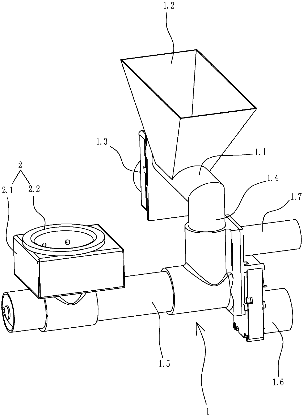
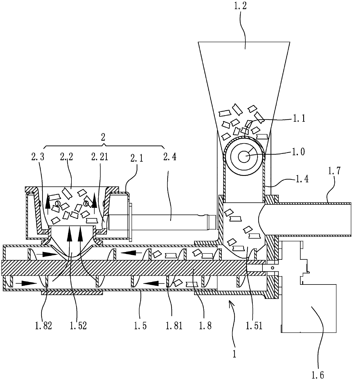
[0025] Specific embodiment one: as figure 1 , figure 2 As shown, an automatic slag cleaning and feeding combustion device includes a feeding device 1 and a combustion device 2 .

[0026] The feeding device 1 includes an upper feeding cylinder 1.1, a lower feeding cylinder 1.5, an air inlet pipe 1.7, an upper feeding auger 1.0 rotatingly arranged in the upper feeding auger, an upper driving motor 1.3 for driving the upper feeding auger, and an upper feeding auger arranged on the upper feeding auger. Feed hopper 1.2 on the outer surface of the cylinder, rotate the lower feeding auger 1.8 arranged in the lower feeding cylinder, the lower driving motor 1.6 for driving the lower feeding auger, and the lower feeding cylinder feeding port arranged on the outer surface of the lower feeding cylinder 1.51 and the lower feeding cylinder discharge port 1.52 that is arranged on the upward opening on the outer surface of the lower feeding cylinder.

[0027] The axis of the upper feeding...


PUM


Abstract

The invention discloses a feeding combustion device with an automatic residue elimination function, and aims at providing a feeding combustion device with an automatic residue elimination function andcapable of effectively separating particle powder generated in a combustion process in time to realize automatic residue elimination, so that the combustion quality of biomass particles is improved.The feeding combustion device with the automatic residue elimination function comprises a feeding device and a combustion device, wherein the feeding device comprises a lower feeding barrel, a lower feeding packing auger rotationally arranged in the lower feeding barrel, a lower feeding barrel charge port formed in the outer side surface of the lower feeding barrel, and a lower feeding barrel discharge port formed in the outer side surface of the lower feeding barrel; spiral blades on the lower feeding packing auger comprise forward-propulsion spiral blades and reverse-propulsion spiral blades; the forward-propulsion spiral blades and the reverse-propulsion spiral blades are located at the two opposite sides of the lower feeding barrel discharge port; and the combustion device comprises acombustion bowl located above the lower feeding barrel discharge port, a material guide barrel through port formed in the bottom surface of the combustion bowl, and a material guide barrel connectingthe combustion bowl with the lower feeding barrel discharge port.

Description

technical field [0001] The invention relates to a fireplace, in particular to an automatic slag cleaning and feeding combustion device applied to the fireplace. Background technique [0002] At present, real fire fireplaces are generally heated and ignited, that is, the fuel particles are heated by the ignition rod, so that the fuel is smoldering to open burning (open flame); the fuel particles are usually fed by a feeding system, and the fuel particles are input into the A burning bowl at the bottom of the hearth of a real fire fireplace. The feeding system of the current real fire fireplace is usually arranged above the furnace, which uses a funnel bin, and the lower part of the funnel bin communicates with the furnace through a feeding channel; when actually feeding, the fuel particles are poured into the funnel bin, and the fuel Under the action of its own weight, the particles gradually fall into the combustion bowl at the bottom of the furnace along the feeding channe...

Claims


Application Information

Patent Timeline
Patent Type & Authority Applications(China)
IPC IPC(8): F24B1/18F24B1/191
Inventor 赵伟忠徐建锋项志垚胡炉林
Owner ZHEJIANG ZHONGLI TOOL MFG
Why Eureka
Try Eureka