Rocket engine micro-force measuring device
A technology of rocket engine and measuring device, which is applied in the direction of measuring device, force/torque/work measuring instrument, force/torque/work measuring instrument calibration/test, etc. and other problems to achieve the effect of improving accuracy, reducing friction and elastic resistance
- Summary
- Abstract
- Description
- Claims
- Application Information
AI Technical Summary
Problems solved by technology
Method used
Image
Examples
Embodiment 1
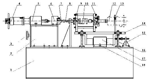
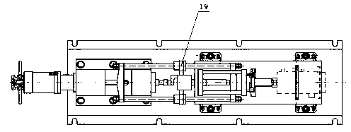
[0025] A rocket engine micro-force measuring device, at least comprising a fixed frame 1 fixedly connected to a test site, characterized in that: a load-bearing pier 2 and an air-floating small displacement device are fixed above the fixed frame 1, and a load-bearing pier 2 is slidably connected with a For the booster device, a force transmission frame 9 is fixed on the side close to the booster device above the small displacement device of the air flotation, and an engine fixing unit is arranged on the side away from the booster device above the small displacement device of the air flotation, and the force transmission frame 9 is close to the booster The outer wall and the inner wall on one side of the device are respectively detachably connected with a force sensor one 8 and a force sensor two 10. When the non-working state is in a non-working state, a force gap is left between the force sensor one 8 and the force-applying device. The force transmission calibration frame 19 o...
Embodiment 2
[0028] Such as figure 1 , figure 2 As shown, it is improved on the basis of Embodiment 1, and the force applying device includes a speed reducer 4, a force booster 5, a force-bearing mount 6 and a force measuring shaft 7, wherein the output shaft of the speed reducer 4 is connected to the force force The input shaft of the booster 5 is connected by transmission, the booster 5 is slidingly connected with the fixed frame 1 along the length direction of the fixed frame 1, the load-bearing mounting seat 6 is fixed on the end of the load-bearing pier 2 away from the force booster 5, and the load-bearing mounting base 6 A force measuring shaft 7 is also fixed on the side close to the force sensor one 8, and a force gap is left between the force sensor one 8 and the force measuring shaft 7 in the non-working state.
[0029]The centerlines of the reducer 4, the force booster 5, the force-bearing mount 6, the force measuring shaft 7, the force sensor one 8, the force transmission fra...
Embodiment 3
[0037] Such as figure 1 , figure 2 As shown, it is improved on the basis of Embodiment 1 and Embodiment 2, and the force sensor-8 is connected with the electrical signal of the external data acquisition equipment, and is used for the real-time force value during feedback test or static calibration; The second sensor 10 is connected with the external display by electric signal, and serves as an instrument for feeding back the current calibration force value during static calibration.
[0038] The external data acquisition equipment is connected with the force sensor-8 by electrical signal, and the data acquisition equipment selects the PC-based measurement and control system of American NI Company, and the NI hardware products are connected to PC or notebook computer through USB or Ethernet. Connect the CompactDAQ chassis to the PC and insert the I / O module with integrated signal conditioning into the chassis. Described external data collection equipment is existing mature t...
PUM
 Abstract
Description
Claims
Application Information
 - R&D
- Intellectual Property
- Life Sciences
- Materials
- Tech Scout
- Unparalleled Data Quality
- Higher Quality Content
- 60% Fewer Hallucinations
Browse by: Latest US Patents, China's latest patents, Technical Efficacy Thesaurus, Application Domain, Technology Topic, Popular Technical Reports.
© 2025 PatSnap. All rights reserved.Legal|Privacy policy|Modern Slavery Act Transparency Statement|Sitemap|About US| Contact US: help@patsnap.com


