Ultrasonic flaw detector

A flaw detector and ultrasonic technology, applied in the field of non-destructive testing equipment, can solve the problems of inconvenient inspection personnel, troublesome carrying, and affecting inspection operations, etc., to improve stability and interaction effects, ensure normal coating, and facilitate cleaning operations Effect

Inactive Publication Date: 2019-04-16
厦门优而特技术咨询服务有限公司
View PDF11 Cites 2 Cited by
  • Summary
  • Abstract
  • Description
  • Claims
  • Application Information

AI Technical Summary

Problems solved by technology

[0004] The above-mentioned existing technical solutions have the following defects: before performing ultrasonic non-destructive testing, it is usually necessary to apply a couplant on the surface of the test object to discharge the air between the probe and the workpiece, so that the ultrasonic waves can effectively penetrate into the workpiece. Side workpiece to ensure the sound intensity transmittance on the detection surface
The existing couplant is usually stored in the bottle, so that when conducting on-site non-destructive testing, it is necessary to carry the testing instrument and the bottle containing the couplant at the same time, which is more troublesome to carry, and it may happen that the couplant bottle is forgotten. Affects the normal detection operation, the separation of the coupling agent bottle and the detection instrument is not convenient for the detection operation of the detection personnel

Method used


Image

  • Ultrasonic flaw detector
  • Ultrasonic flaw detector
  • Ultrasonic flaw detector

Examples


Embodiment

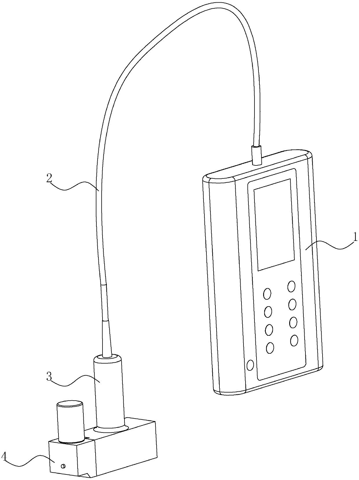
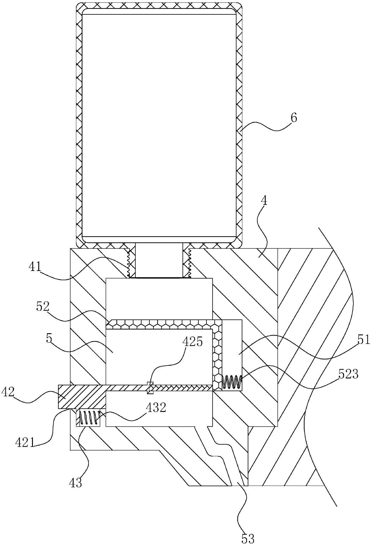
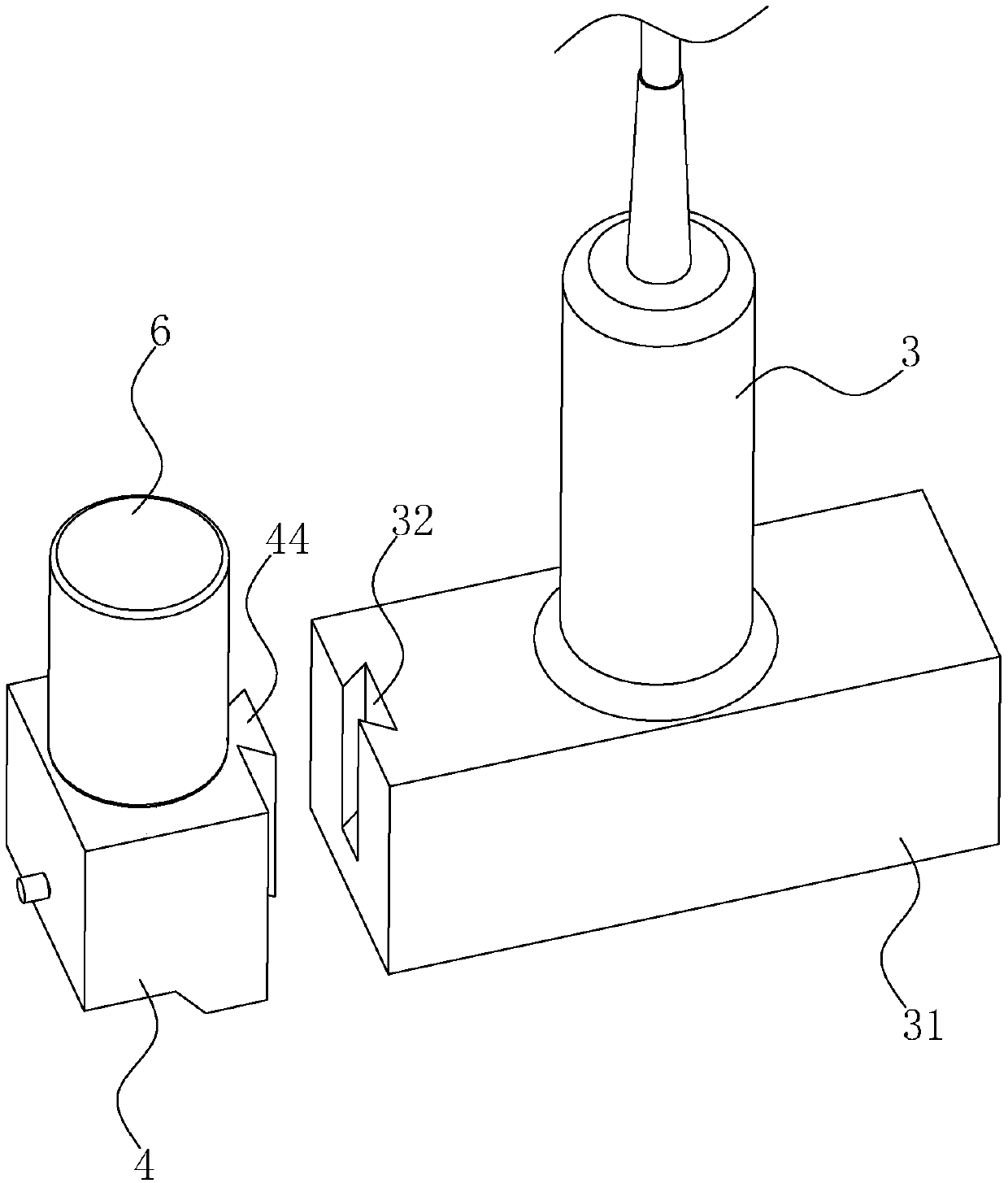
[0036] An embodiment, an ultrasonic flaw detector, such as figure 1 , 2 As shown, it includes a detection host 1, a transmission line 2 connected to the detection host 1, and a probe 3 detachably connected to the end of the transmission line 2. The probe 3 is provided with a placement seat 4 on the side wall of the housing, and the placement seat 4 is provided with a housing Cavity 5, the top of the placement seat 4 is provided with a threaded through hole 41 communicating with the containing cavity 5, the threaded through hole 41 is threadedly connected with a solvent bottle 6 containing a couplant; the placement seat 4 is located in the cavity on the side of the containing cavity 5 A sliding groove 51 is provided on the side wall of the body, and a shielding assembly 52 for closing the accommodating cavity 5 is horizontally slidably arranged in the sliding groove 51; the placement seat 4 is located on the side wall of the cavity on the other side of the accommodating cavity 5. ...


PUM


Abstract

The invention discloses an ultrasonic flaw detector, which relates to the technical field of nondestructive testing equipment, and solves the technical problem that the separation setting of a coupling agent bottle and a detection instrument is not convenient for detection by detection personnel. The ultrasonic flaw detector is technically characterized by comprising a detection host, a transmission line connected onto the detection host and a probe detachably connected onto the tail end of the transmission line, wherein the side wall of the shell of the probe is provided with a placement seat; the placement seat is internally provided with an accommodation cavity; the top of the placement seat is provided with a threaded through hole communicated with the accommodation cavity; a solvent bottle loaded with the coupling agent is in threaded connection to the threaded through hole; the cavity side wall, located at one side of the accommodation cavity, of the placement seat is provided with a sliding groove; the sliding groove is internally provided with a shielding assembly for sealing the accommodation cavity in a horizontal sliding mode; the cavity side wall, located at the other side of the accommodation cavity, of the placement seat is provided with a driving assembly for controlling the shielding assembly to slide along the sliding groove; and the bottom part of the accommodation cavity is provided with a liquid outlet channel communicated with the bottom surface of the placement seat. The ultrasonic flaw detector has the advantage of facilitating flaw detection by the detection personnel.

Description

Technical field [0001] The invention relates to the technical field of non-destructive testing equipment, and more specifically, it relates to an ultrasonic flaw detector. Background technique [0002] A Chinese patent with publication number CN107525854A discloses a new type of ultrasonic flaw detector, including a neck strap, one end of the neck strap is provided with a strap buckle, and the other end of the neck strap is provided with a detector host, the detector The end of the main body away from the neck strap is provided with a neck strap lever, and the left and right sides of the main body of the detector are provided with brackets, the lower end of the bracket is provided with a transmission line, the bottom side of the main body of the detector is provided with a waist belt, and the detector The other side of the bottom end of the host is provided with a waist belt clamp lever, the end of the waist belt away from the main body of the tester is provided with a waist belt...

Claims


Application Information

Patent Timeline
Patent Type & Authority Applications(China)
IPC IPC(8): G01N29/22G01N29/28
CPCG01N29/22G01N29/28
Inventor 何福荣
Owner 厦门优而特技术咨询服务有限公司
Why Eureka
Try Eureka