Full-tensor magnetic gradient measurement system mounting error calibration device and calibration method

A technology of installation error and measurement system, which is applied to measurement devices, measurement of magnetic variables, navigation through velocity/acceleration measurement, etc. Simple to use effects

Active Publication Date: 2019-04-16
SHANGHAI INST OF MICROSYSTEM & INFORMATION TECH CHINESE ACAD OF SCI
View PDF5 Cites 7 Cited by
  • Summary
  • Abstract
  • Description
  • Claims
  • Application Information

AI Technical Summary

Problems solved by technology

[0007] In view of the shortcomings of the prior art described above, the purpose of the present invention is to provide a calibration device and a calibration method for the installation error of the full tensor magnetic gradient measurement system, so as to solve the problem that the prior art cannot provide a simple and convenient calibration device. and calibration problems

Method used


Image

  • Full-tensor magnetic gradient measurement system mounting error calibration device and calibration method
  • Full-tensor magnetic gradient measurement system mounting error calibration device and calibration method
  • Full-tensor magnetic gradient measurement system mounting error calibration device and calibration method

Examples


Embodiment 1

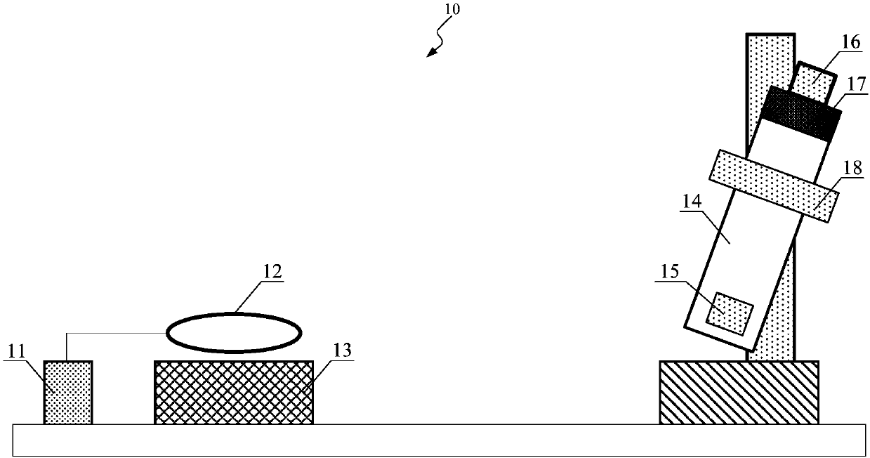
[0076] like figure 1 As shown, this embodiment provides a calibration device 10 for the installation error of the full tensor magnetic gradient measurement system, and the calibration device 10 includes:

[0077] An excitation source 11, configured to provide an excitation signal;

[0078] A calibration source 12, electrically connected to the excitation source 11, for generating a calibration magnetic field driven by the excitation source 11;

[0079] A non-magnetic placement platform 13, located below the calibration source 12, is used to provide a placement platform;

[0080] The mounting bracket 14 is arranged on one side of the calibration source 12 for providing a mounting platform;

[0081] A full tensor magnetic gradient measurement component 15 is arranged on the mounting bracket 14 for measuring the magnetic field gradient value generated by the calibration source 12 at the full tensor magnetic gradient measurement component 15;

[0082] The combined inertial navi...

Embodiment 2

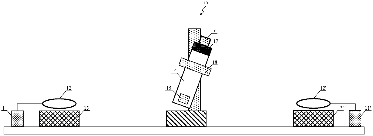
[0103] like image 3 As shown, this embodiment provides a calibration device for the installation error of a full tensor magnetic gradient measurement system. The difference between it and Embodiment 1 is that the calibration device 10 described in this embodiment also includes:

[0104] Auxiliary excitation source 11', for providing auxiliary excitation signal;

[0105] An auxiliary calibration source 12', electrically connected to the auxiliary excitation source 11', for generating an auxiliary calibration magnetic field driven by the auxiliary excitation source 11';

[0106] Auxiliary non-magnetic placement table 13', located below the auxiliary calibration source 12', for providing a placement platform;

[0107] Wherein, the excitation source 11 and the auxiliary excitation source 11' are synchronously driven, and the calibration source 12 and the auxiliary calibration source 12' are arranged symmetrically with respect to the measuring point of the full tensor magnetic gr...

Embodiment 3

[0114] like Figure 4 As shown, this embodiment provides a calibration device for the installation error of a full tensor magnetic gradient measurement system, which is different from Embodiment 2 in that the calibration source 12 and the auxiliary The calibration source 12' is driven by the same source.


PUM

PropertyMeasurementUnit
Diameteraaaaaaaaaa
Magnetic momentaaaaaaaaaa

Abstract

The invention provides a full-tensor magnetic gradient measurement system mounting error calibration device and a calibration method. The calibration device comprises an excitation source, a calibration source electrically connected to the excitation source, a non-magnetic placement platform arranged below the calibration source, a mounting bracket arranged at one side of the calibration source, afull-tensor magnetic gradient measurement assembly arranged on the mounting bracket, combined inertial navigation rigidly connected to the full-tensor magnetic gradient measurement assembly, a measurement and control assembly electrically connected to the full-tensor magnetic gradient measurement assembly and the combined inertial navigation, and an attitude adjustment device arranged at one sideof the calibration source. Through the full-tensor magnetic gradient measurement system mounting error calibration device and the calibration method provided in the invention, the problem that a simple and convenient calibration device and a calibration method can not be provided in the prior art can be solved.

Description

technical field [0001] The invention relates to the calibration of the installation error of a full tensor magnetic gradient measurement system, in particular to a calibration device and a calibration method for the installation error of a full tensor magnetic gradient measurement system. Background technique [0002] The full tensor magnetic gradient describes the change rate information of the magnetic field vector in three-dimensional space, that is, the gradient of the three components of the magnetic field vector in three directions in space. The measurement results of the full tensor magnetic gradient have the advantages of being less affected by the magnetization direction, can reflect the vector magnetic moment information of the target body, and can better invert the field source parameters (orientation, magnetic moment, etc.), so it can be used for the field source Carry out positioning and tracking, and improve the resolution of the magnetic source body. The meas...

Claims


Application Information

Patent Timeline
IPC IPC(8): G01R33/00G01C1/00G01C21/16
CPCG01C1/00G01C21/16G01R33/0023
Inventor 伍俊荣亮亮张国锋邱隆清张树林张朝祥裴易峰代海宾尤立星谢晓明
Owner SHANGHAI INST OF MICROSYSTEM & INFORMATION TECH CHINESE ACAD OF SCI
Why Eureka
Try Eureka