System and method for compensating automobile laser radar obstacle recognition blind area

A lidar and obstacle technology, applied in the field of vehicle obstacle recognition, can solve the problems of large amount of data calculation and more data processing, and achieve the effect of fast processing and transmission, improving safety and responsiveness

Pending Publication Date: 2019-04-16
ZHEJIANG CRRC ELECTRIC VEHICLE CO LTD
View PDF4 Cites 15 Cited by
  • Summary
  • Abstract
  • Description
  • Claims
  • Application Information

AI Technical Summary

Problems solved by technology

[0004] The above-mentioned algorithm for merging ultrasonic radar and laser radar for obstacle recognition first needs to generate obstacle grid information, and then fuse the radar data in the grid information to eliminate detection blind spots, which requires a large amount of data calculation and more data processing. And during the operation of the vehicle, the reaction speed and recognition sensitivity largely determine the safety of the vehicle

Method used


Image

  • System and method for compensating automobile laser radar obstacle recognition blind area
  • System and method for compensating automobile laser radar obstacle recognition blind area
  • System and method for compensating automobile laser radar obstacle recognition blind area

Examples


Embodiment 1

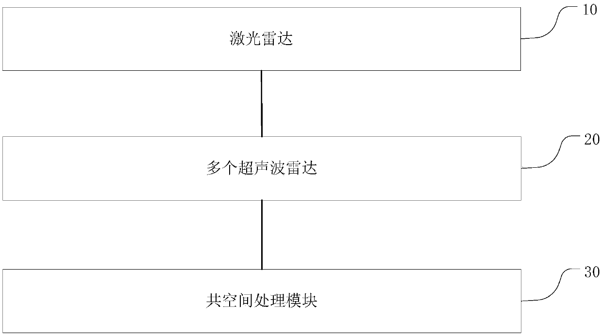
[0050] This embodiment provides a system for compensating the blind area of ​​obstacles recognized by the automotive lidar, such as Figure 1 to Figure 4 As shown, the system includes:

[0051] Lidar, used to obtain preset point cloud data information of obstacles within the preset scanning range;

[0052] Multiple ultrasonic radars are used to obtain preset point data information corresponding to obstacles within the preset sensing range;

[0053] The co-space processing module, according to the preset time clustering processing method, performs preset time clustering processing on the acquired preset point cloud data and preset point data, and obtains the current vehicle preset sensing range and preset scanning range at the same time obstacle information.

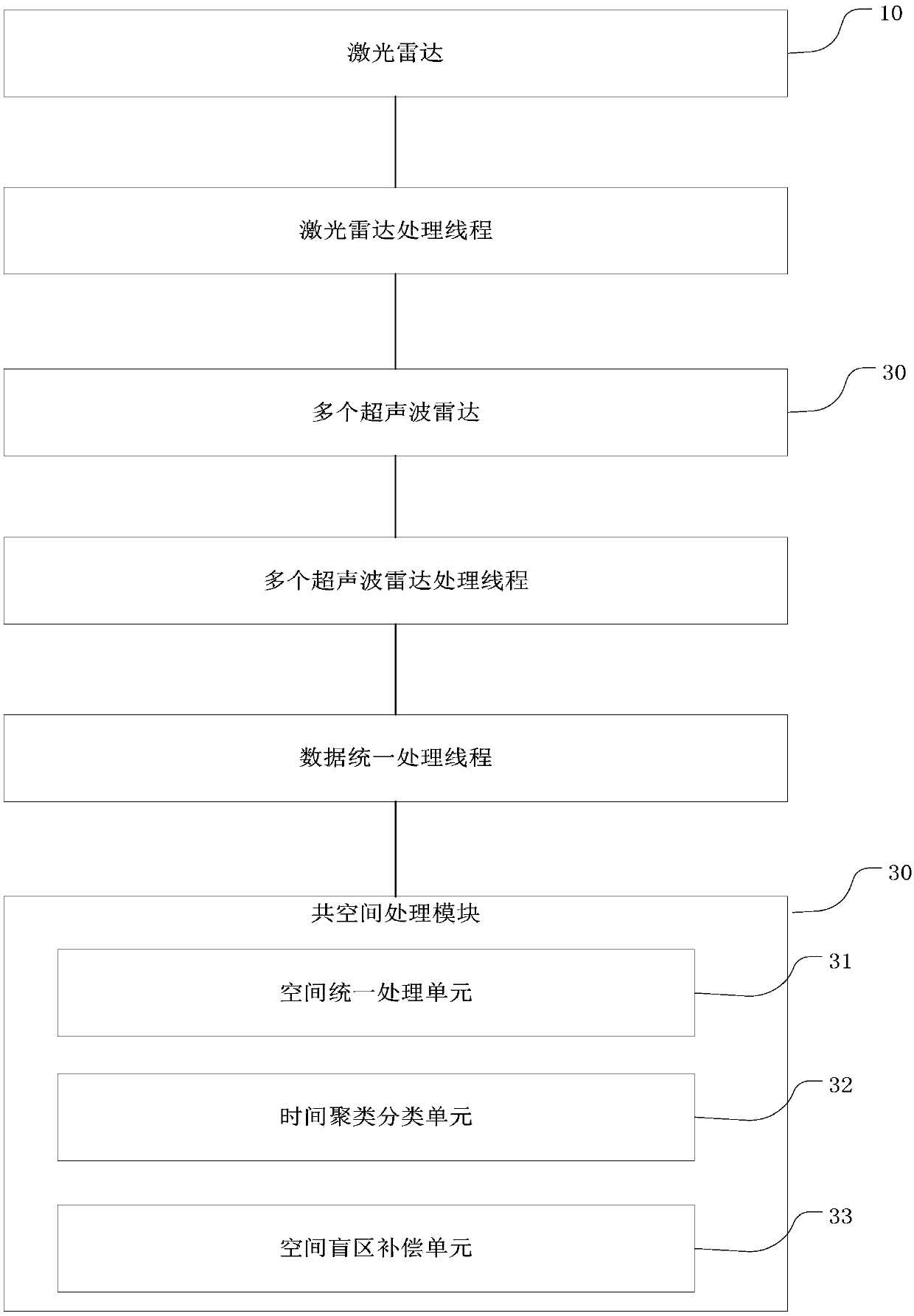
[0054] Further, include:

[0055] The laser radar processing thread is used to transmit the preset point cloud data information obtained by the laser radar;

[0056] Multiple ultrasonic radar processing threads are us...

Embodiment 2

[0073] This embodiment provides a system for detecting ground obstacles based on laser radar, such as Figure 5 to Figure 6 As shown, the method for compensating the blind area of ​​obstacles identified by automotive lidar includes steps:

[0074] S1: Obtain preset point cloud data information of obstacles within the preset scanning range through lidar;

[0075] S2: Obtain preset point data information corresponding to obstacles within the preset sensing range through multiple ultrasonic radars;

[0076] S3: Obtain preset point cloud data information and preset point data information through the data unified data processing thread, and perform preset time clustering on the acquired preset point cloud data and preset point data according to the preset time clustering processing method Processing to obtain obstacle information within the preset sensing range and preset scanning range of the current car at the same time.

[0077] Further, step S2 includes:

[0078] S21: Obtain...


PUM


Abstract

The invention provides a system for compensating an automobile laser radar obstacle recognition blind area, and solves the problem that in the prior art, the blind area exists when a laser radar recognizes an obstacle in a preset range of the automobile. The system comprises a laser radar used for acquiring preset point cloud data information of the obstacle in a preset scanning range, a pluralityof ultrasonic radars used for acquiring preset point data information corresponding to the obstacle in a preset sensing range, and a common space processing module which performs preset time clustering processing on the acquired preset point cloud data and preset point data according to a preset time clustering processing method to acquire obstacle information in the preset sensing range and thepreset scanning range of the current automobile at the same moment. By adopting the system, compensation of blind areas between the laser radar and the ultrasonic radars at different positions at thesame moment can be realized, the blind area of the laser radar obstacle recognition is compensated through few data, and the driving safety of the automobile is further improved.

Description

technical field [0001] The invention relates to the technical field of vehicle obstacle recognition, in particular to a system and method for compensating for blind areas of vehicle laser radar recognition obstacles. Background technique [0002] Lidar obtains point cloud information of the surrounding environment through scanning and ranging, which has high precision, long distance, fast speed, and is not affected by light. It has broad application prospects in the field of unmanned vehicles and robots. [0003] However, the laser radar has an angle limit in the identification process, and it is easy to have blind spots in the identification, which increases the danger in the driving process of the car. Therefore, it is necessary to propose a system that compensates for the blind spots in the laser radar recognition; Identification of automobile obstacles, for example, the patent number is: The present invention discloses a laser radar and ultrasonic radar information fusi...

Claims


Application Information

Patent Timeline
Patent Type & Authority Applications(China)
IPC IPC(8): G01S17/93G01S17/02G01S15/02G01S15/93
CPCG01S15/931G01S15/86G01S17/86G01S17/931
Inventor 胡远敏何安清张培颜祺宇黄帅
Owner ZHEJIANG CRRC ELECTRIC VEHICLE CO LTD
Why Eureka
Try Eureka