
Medical imaging diagnosis auxiliary device

A diagnostic aid and medical imaging technology, applied in optics, optical components, instruments, etc., can solve problems such as the inability to meet the effect of simultaneous effective observation by observers, and the inability to meet the observation needs of observers at different heights, and achieve the effect of meeting the needs of use

Inactive Publication Date: 2019-04-16
赵书才
View PDF9 Cites 3 Cited by
  • Summary
  • Abstract
  • Description
  • Claims
  • Application Information

AI Technical Summary

Problems solved by technology

[0003] In clinical diagnosis, image observation light boxes are usually used to observe films such as CT films. The general light boxes are fixed and cannot meet the observation needs of observers at different heights. When the light box observation CT film is used for multi-person meetings or teaching, etc. , cannot meet the effect of effective observation by observers from all angles at the same time. Therefore, the present invention proposes a medical imaging diagnosis auxiliary device

Method used


Image

  • Medical imaging diagnosis auxiliary device
  • Medical imaging diagnosis auxiliary device
  • Medical imaging diagnosis auxiliary device

Examples


Embodiment 1

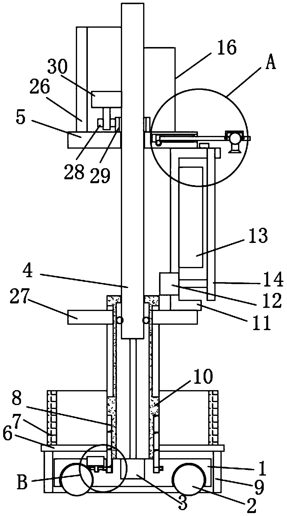
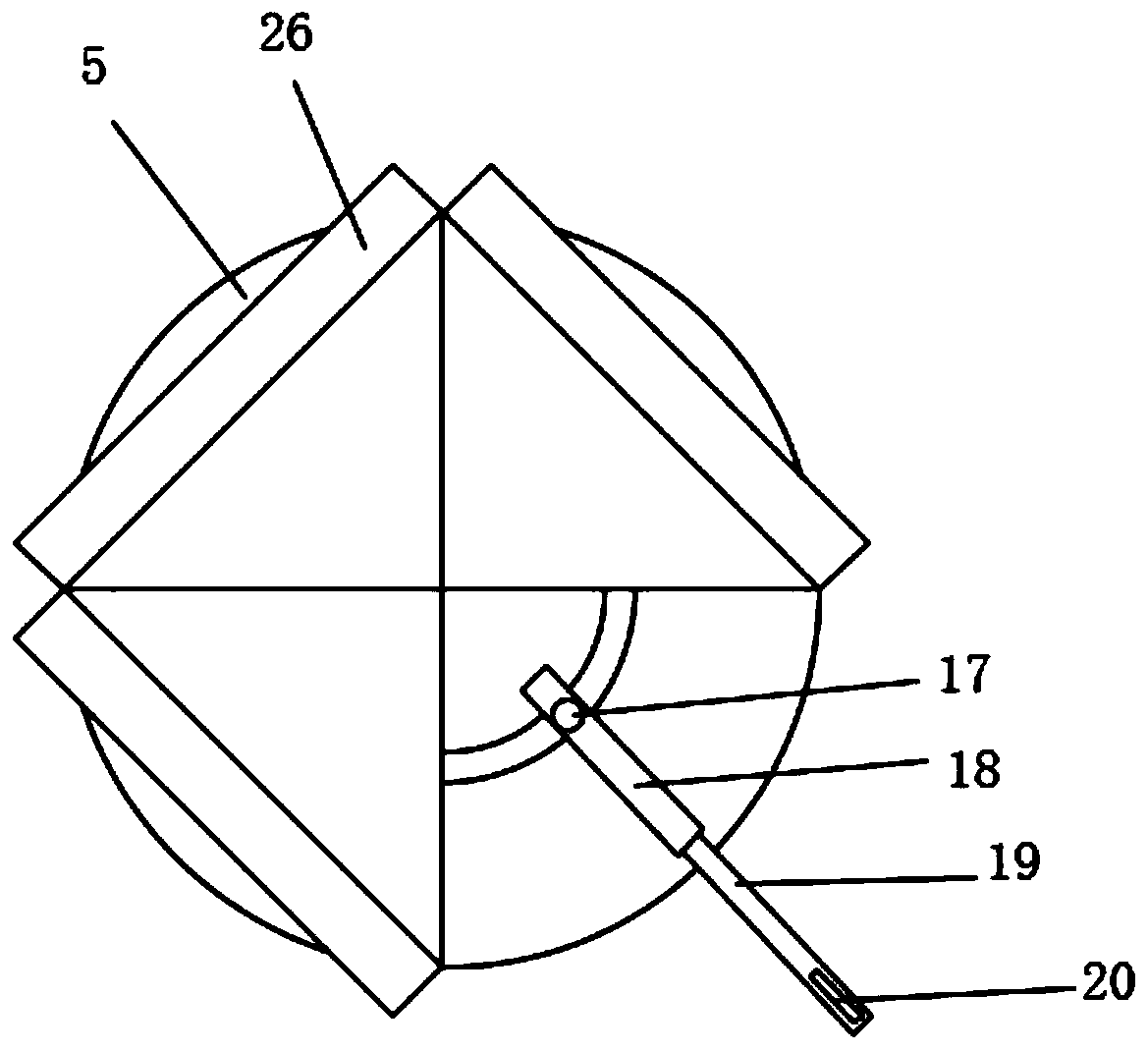
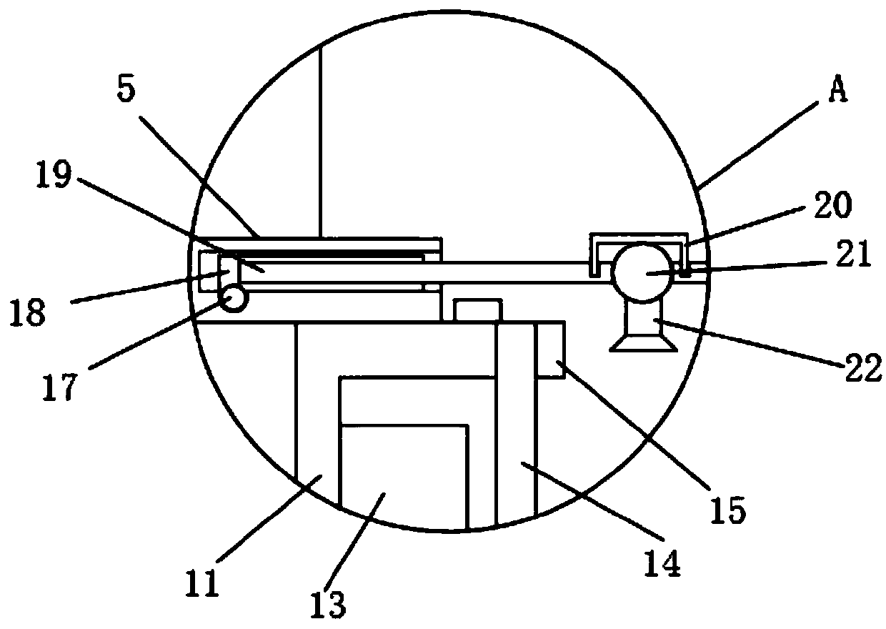
[0027] see Figure 1-4 , a medical imaging diagnosis auxiliary equipment, comprising a base 1, the bottom end of the base 1 is movably connected with universal rollers 2, and the universal rollers 2 are distributed on the base 1 in an annular array, and the upper end of the base 1 is fixedly installed with a ring pipe 10, And the base 1 is embedded with the first hydraulic cylinder 3 facing the seat surface of the ring pipe 10, the free end of the first hydraulic cylinder 3 extends into the lumen of the ring pipe 10, and the extension end is fixedly installed with a lifting column 4, and the bottom end of the lifting column 4 Guide balls are installed on the column wall, and the guide balls are distributed in a circular array along the lifting column 4, and the guide balls are attached to the inner pipe wall of the ring pipe 10, and the guide balls are set to ensure that the lifting column 4 is more flexible and effective when it is lifted.

[0028] The end of the lifting colu...

Embodiment 2

[0037] see Figure 1-4, a medical imaging diagnosis auxiliary equipment, comprising a base 1, the bottom end of the base 1 is movably connected with universal rollers 2, and the universal rollers 2 are distributed on the base 1 in an annular array, and the upper end of the base 1 is fixedly installed with a ring pipe 10, And the base 1 is embedded with the first hydraulic cylinder 3 facing the seat surface of the ring pipe 10, the free end of the first hydraulic cylinder 3 extends into the lumen of the ring pipe 10, and the extension end is fixedly installed with a lifting column 4, and the bottom end of the lifting column 4 Guide balls are installed on the column wall, and the guide balls are distributed in a circular array along the lifting column 4, and the guide balls are attached to the inner pipe wall of the ring pipe 10, and the guide balls are set to ensure that the lifting column 4 is more flexible and effective when it is lifted.

[0038] The end of the lifting colum...


PUM


Abstract

The invention discloses a medical imaging diagnosis auxiliary device. The medical imaging diagnosis auxiliary device comprises a pedestal, a bottom end of the pedestal is movably connected with a universal wheel, and the universal wheel is distributed on the pedestal in the shape of a ring-shaped array, a ring tube is fixedly mounted on an upper end of the pedestal, and a first hydraulic cylinderis embedded on a base surface of the ring tube, and a free end of the first hydraulic cylinder stretches into a tube cavity of the ring tube. In the medical imaging diagnosis auxiliary device, a lightbox is arranged on a rotatable first disk block, moreover, the first disk block is provided with a plurality of display screens which surround the light box and are in the shape of a ring-shaped array, main analyzers and hearers of a radiograph film respectively can be at each side of the light box and the display screens, thus, when the light box is used for a multi-party conference or teaching,satisfying an effect that observers at each angle can simultaneously and effectively observe is guaranteed. The medical imaging diagnosis auxiliary device is provided with the pedestal comprising theuniversal wheel, and periphery of the pedestal is provided with a liftable locating cover, thus, movement or locating of the medical imaging diagnosis auxiliary device can be controlled flexibly, meanwhile, a net is arranged on a threaded disk, so, an effect of temporarily collecting and placing the radiograph film is realized.

Description

technical field [0001] The invention relates to the technical field of medical equipment, in particular to an auxiliary equipment for medical image diagnosis. Background technique [0002] Medical imaging refers to the technology and processing process of obtaining internal tissue images of the human body or a certain part of the human body in a non-invasive manner for medical treatment or medical research. It includes the following two relatively independent research directions: medical imaging system and medical image processing. The former refers to the process of image formation, including the research on imaging mechanism, imaging equipment, imaging system analysis and other issues; the latter refers to the further processing of the obtained image, the purpose of which is to make the original image that is not clear enough Restoration, or to highlight certain feature information in the image, or to classify the image as a pattern, etc. [0003] In clinical diagnosis, ...

Claims


Application Information

Patent Timeline
Patent Type & Authority Applications(China)
IPC IPC(8): G02B27/02
CPCG02B27/026G02B27/028
Inventor 赵书才李伟宏赵文端
Owner 赵书才
Learn More