Tool wear state identification method based on vibration and acoustic emission

A technology for tool wear and state recognition, applied in character and pattern recognition, neural learning methods, registration/indicating machine work, etc., can solve problems such as inability to apply, immature tool state monitoring technology, etc., achieve sensitivity, easy installation, The effect of high sensitivity

Pending Publication Date: 2019-04-16
KUNMING UNIV OF SCI & TECH
View PDF3 Cites 10 Cited by
  • Summary
  • Abstract
  • Description
  • Claims
  • Application Information

AI Technical Summary

Problems solved by technology

However, the current tool condition monitoring technology

Method used


Image

  • Tool wear state identification method based on vibration and acoustic emission

Examples


Embodiment 1

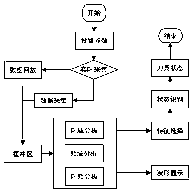
[0014] Embodiment 1: as figure 1 As shown, a tool wear state recognition method based on vibration and acoustic emission, the method steps are as follows:

[0015] The method steps are as follows:

[0016] S1. Collect vibration signals in cutting processing through vibration signal acquisition equipment, and collect acoustic emission signals in cutting processing through acoustic emission signal acquisition equipment (vibration signal acquisition equipment and acoustic emission signal acquisition equipment need to set sampling parameters: such as sampling time, sampling frequency, number of sampling points);

[0017] S2. Vibration signal and acoustic emission signal are respectively based on the amount of the three cutting elements and the wear state of the tool (according to the needs of processing, the wear state of the tool is divided into three stages: initial wear of the new knife, normal wear, and severe wear. In order to obtain these three For tools with different deg...


PUM


Abstract

The invention discloses a tool wear state identification method based on vibration and acoustic emission, and belongs to the technical field of advanced manufacturing. According to the invention, advantages and disadvantages of various monitoring signals are analyzed; vibration and acoustic emission signals which are high in sensitivity and easy to install are selected as monitoring signals, and by completing signal collection and analysis, feature extraction and optimal feature selection, tool wear state recognition is finally achieved, and tool wear states of the three stages of initial wear, normal wear and severe wear are output.

Description

technical field [0001] The invention relates to a tool wear state identification method based on vibration and acoustic emission, which belongs to the field of advanced manufacturing technology. Background technique [0002] Tool condition monitoring technology is a key technology developed on the basis of sensor technology, signal analysis technology, pattern recognition technology and computer technology. Through real-time monitoring of the tool wear status, the processing quality of the product can be improved, the production cost can be reduced, and the production efficiency can be improved. It is an indispensable key technology for truly realizing automation and intelligent production. However, the current tool condition monitoring technology is not mature enough to be used in actual processing. Contents of the invention [0003] The invention provides a tool wear state recognition method based on vibration and acoustic emission, which is used for the recognition of...

Claims


Application Information

Patent Timeline
IPC IPC(8): G06K9/62G06N3/08G07C3/00
CPCG06N3/084G07C3/005G06F18/211G06F18/214
Inventor 杜茂华王沛鑫
Owner KUNMING UNIV OF SCI & TECH
Why Eureka
Try Eureka