OLED illumination panel

A panel and substrate technology, applied in the field of organic electroluminescent devices, can solve the problems of special-shaped light-emitting shape, high aspect ratio of light-emitting area, uneven brightness distribution, etc.

Active Publication Date: 2019-04-16
GUAN YEOLIGHT TECH CO LTD
View PDF10 Cites 4 Cited by
  • Summary
  • Abstract
  • Description
  • Claims
  • Application Information

AI Technical Summary

Problems solved by technology

However, in the prior art, when the light-emitting area of ​​the OLED screen is large or the light-emitting shape is irregular, or the aspect ratio of the light-emitting area is high, the brightness distribution will be uneven, which needs to be improved urgently.

Method used


Image

  • OLED illumination panel
  • OLED illumination panel
  • OLED illumination panel

Examples


Embodiment 1

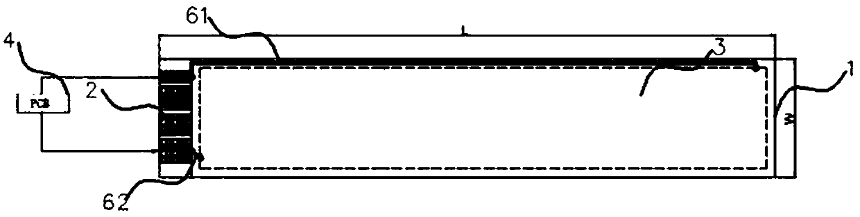
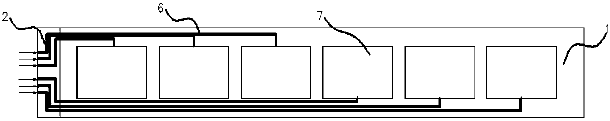
[0026] Please refer to figure 1 and figure 2 , an OLED lighting panel is specifically disclosed in this embodiment.

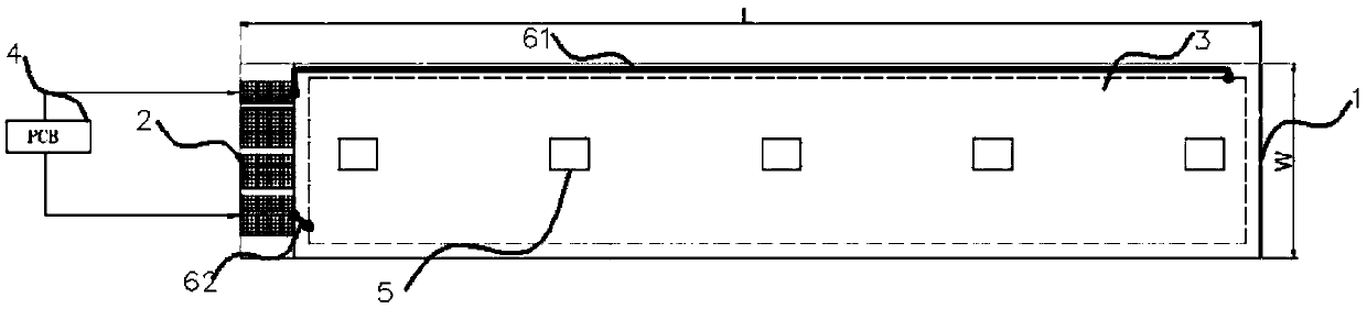
[0027] An OLED lighting panel, comprising: a substrate 1, the substrate 1 comprising: a bonding area 2, an effective light emitting area 3 and a non-effective light emitting area; the effective light emitting area 3, comprising: a first electrode formed on the substrate 1 , a light-emitting layer formed on the first electrode and a second electrode formed on the light-emitting layer; the non-effective light-emitting area is located around the effective light-emitting area 3 .

[0028] in:

[0029] Substrate 1, the basic component of this embodiment, is used to prepare other functional layers on it, including: a first electrode formed on the substrate 1, a light-emitting layer formed on the first electrode, and a second electrode formed on the light-emitting layer .

[0030] The first electrode, the light emitting layer and the second electrode form an effe...


PUM


Abstract

The invention provides a specific structure of an OLED illumination panel. In the technical scheme, on the basis of the prior art, a dispatching lead is disposed in a non-effective light emitting areato introduce an electrical signal in a binding area into an effective light emitting area. Preferably, a PWM wave generated by a single chip microcomputer in a printed circuit board is input into a driving chip, and modulation waveforms with different pulse widths can be output through the scheduling lead. Finally, the on-off control of the effective light emitting area of an OLED screen body isrealized by introducing the modulation waveform on the effective light emitting area of the OLED screen body, and in addition, the brightness uniformity of the screen body is adjusted by adjusting theduty ratio and the amplitude of the modulation waveform.

Description

technical field [0001] The present disclosure generally relates to the technical field of organic electroluminescent devices, and specifically relates to an OLED lighting panel. Background technique [0002] OLED devices usually have a sandwich structure, and a glass substrate or a flexible substrate is covered with an anode with good light transmission, such as indium tin oxide (English full name is Indium Tin Oxide, referred to as ITO), and a hole injection layer is sequentially deposited on the ITO anode. , hole transport layer, organic light-emitting layer, electron transport layer, electron injection layer and other functional layers, then vapor-deposit cathode metal materials, and finally package. [0003] Traditional OLED lighting modules are mostly in the form of an OLED screen plus an FPC, that is, the lighting and brightness adjustment functions are realized through an external control board to achieve the purpose of lighting. However, in the prior art, when the l...

Claims


Application Information

Patent Timeline
Patent Type & Authority Applications(China)
IPC IPC(8): G09G3/3225G09G3/3208H01L51/52H01L27/32
CPCG09G3/3208G09G3/3225G09G2320/0233H10K59/131H10K50/80
Inventor 鲁天星郑彬郭晓磊吴海燕张国辉王静
Owner GUAN YEOLIGHT TECH CO LTD
Why Eureka
Try Eureka