
Change-over switch with convenient switching function

A transfer switch, convenient switching technology, applied in the direction of electrical switches, contacts, electrical components, etc., can solve the problems of laborious movement, no positioning design, and the transfer switch cannot reliably complete the connection of different circuits, achieving easy operation and complete functions. , Simple and reasonable design

Inactive Publication Date: 2019-04-16
广东求精电气有限公司
View PDF0 Cites 0 Cited by
  • Summary
  • Abstract
  • Description
  • Claims
  • Application Information

AI Technical Summary

Problems solved by technology

The current change-over switch generally uses a spring seat, spring and contacts embedded in the switch body. By pushing the spring seat to move longitudinally in the switch body, the spring contacts with different contacts to realize the connection of different circuits. However, there is no positioning design during the movement process, which leads to switching The connection of different circuits cannot be reliably completed in the switch, and if the spring and the contact need to be reliably connected, they must touch each other very tightly, but the tight contact between the spring and the contact will make it difficult to move

Method used


Image

  • Change-over switch with convenient switching function
  • Change-over switch with convenient switching function
  • Change-over switch with convenient switching function

Examples


Embodiment Construction

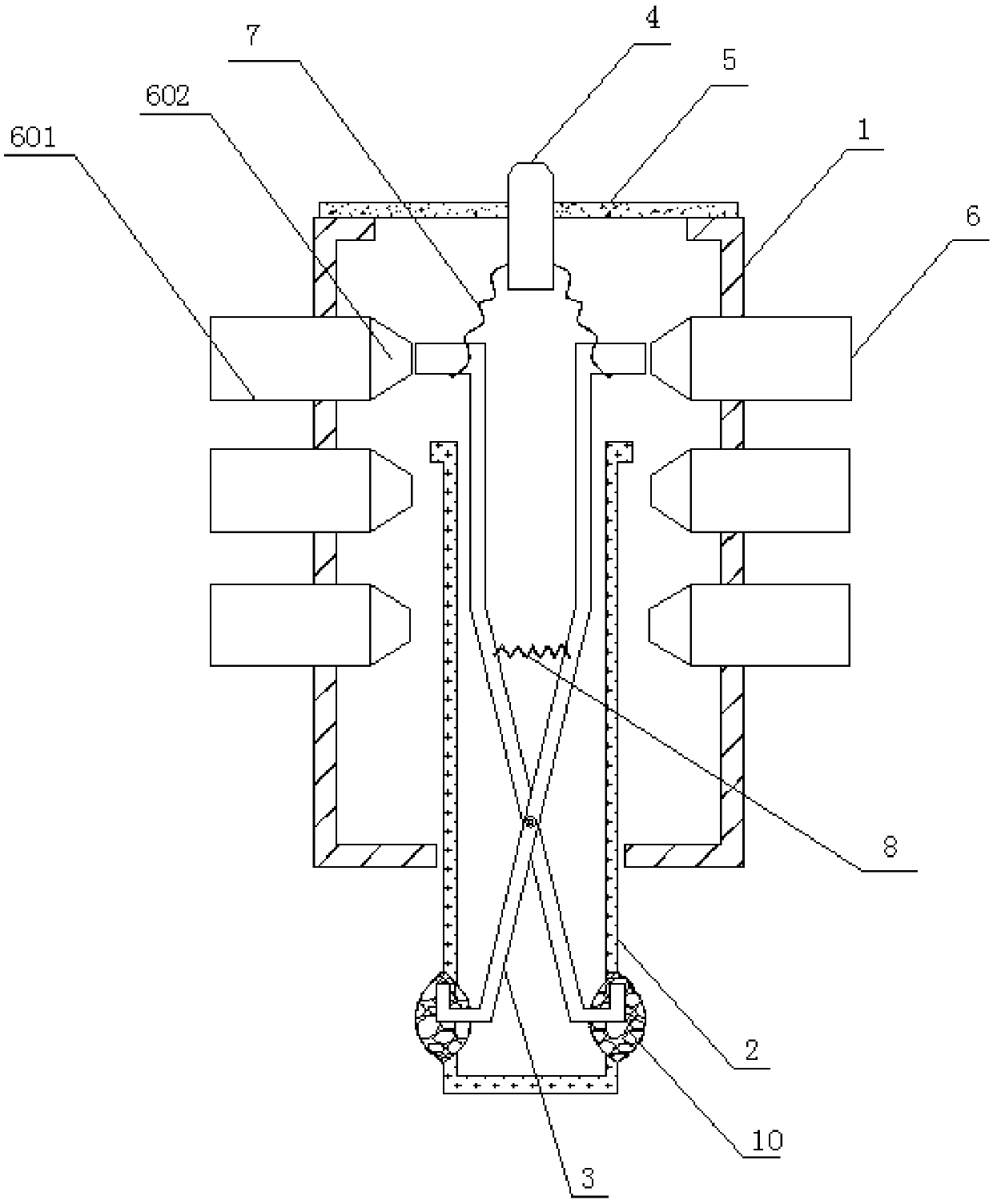
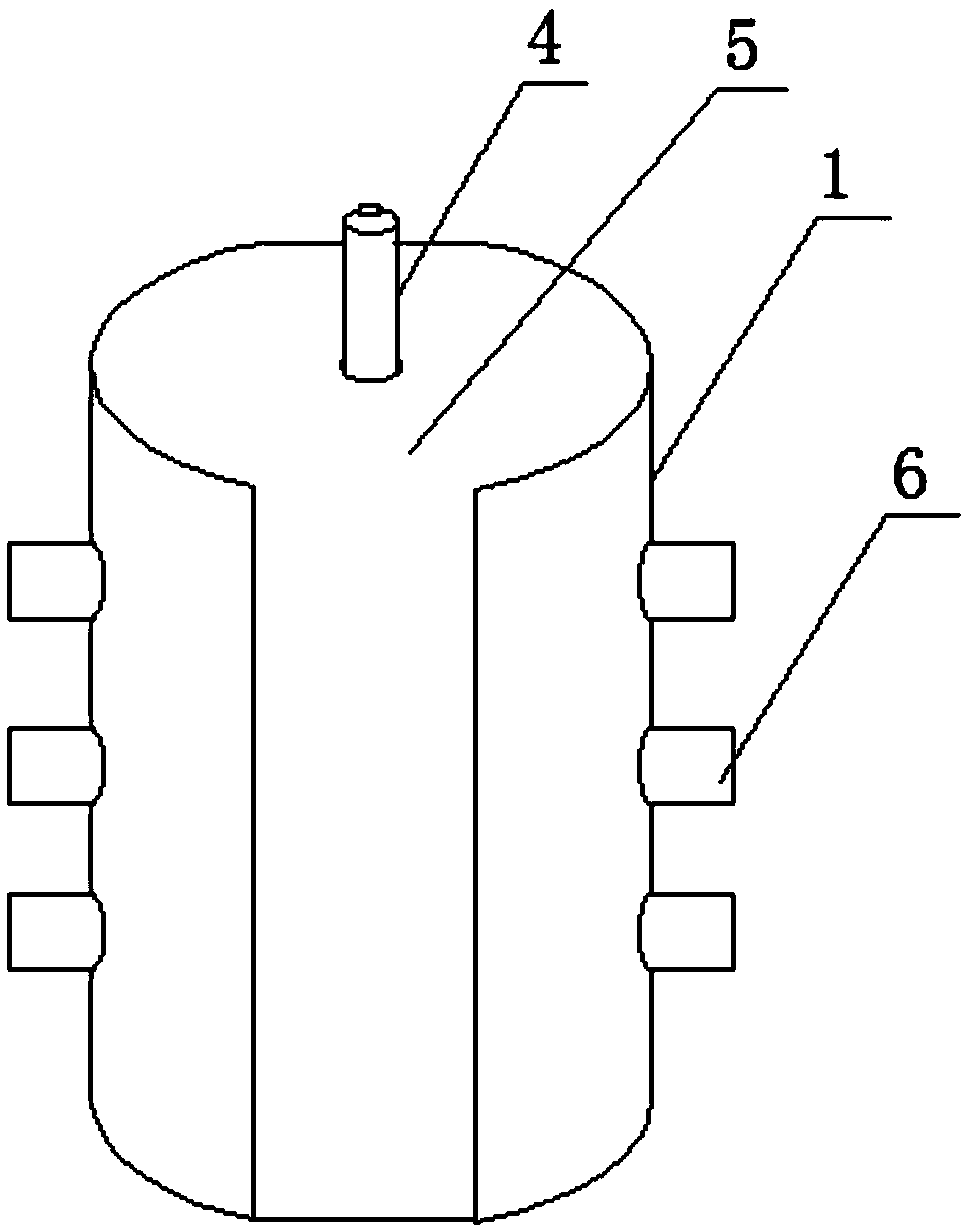
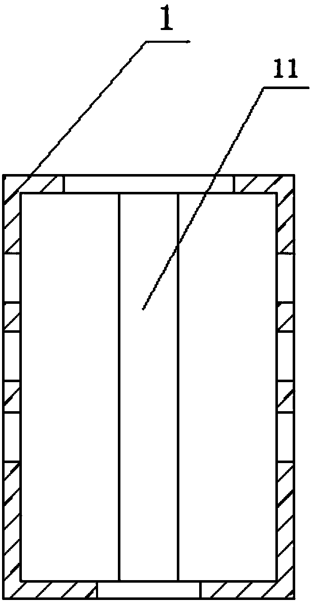
[0026] In order to further explain the technical solution of the present invention, the present invention will be described in detail below through specific examples. It should be noted that all the drawings are in a very simplified form and use imprecise scales, and are only used to facilitate and clearly assist the purpose of illustrating the embodiments of the present invention.

[0027] Such as Figure 1-6 As shown, the present invention provides a changeover switch that is convenient to switch, including a switch body 1, a switch pin seat 2, a conductor 3, a conductive rod 4 and a contact 6, the switch body 1 is a hollow cylinder, and the center of the bottom of the switch is A through hole is provided, and a plurality of pairs of holes are symmetrically provided on the side wall for the contact 6 to be inserted and fixed. Each pair of holes is a switch, which can be connected to a conduction loop. The cylinder cross section of the switch body 1 is circular or rectangul...


PUM


Abstract

The invention provides a change-over switch with a convenient switching function. The change-over switch comprises a switch body, a switch pin seat, an electric conductor, an electric conducting rod and a contact, wherein the switch body is a hollow cylinder, a through hole is formed in the center of the bottom of the switch body, and a plurality of pairs of holes are symmetrically arranged on theside wall of the switch body for the contact to be inserted and fixed; the switch pin seat is a hollow cylinder and can move longitudinally along the inside of the switch body; the electric conductoris in a scissor structure and is arranged in the hollow part of the switch pin seat, one end of the electric conductor is an operating end and is connected with the other end of the switch pin seat,and the other end of the electric conductor is a conductive end, extends out of the hollow part of the switch pin seat, and can touch the contact; an elastic element is connected between the conductive ends; the electric conducting rod is fixedly arranged on the top of the switch body and is electrically connected with the conductive end through a lead; a vertical groove is formed in the inner wall of the switch body, a convex strip is arranged on the switch pin seat, and the convex strip and the vertical groove can be clamped with each other. According to the scheme of the invention, accuratepositioning can be realized, the reliable connection between the conductive end and the contact can be realized, and the conductive end does not hinder movement when transforming different circuits.

Description

technical field [0001] The invention relates to the technical field of a circuit switch, in particular to a transfer switch for easy switching. Background technique [0002] In the electromechanical field, the circuit transfer switch plays a pivotal role, because the reliability of the circuit transfer switch is related to the on-off of the circuit and the accuracy of the original state judgment and detection of the circuit, which is one of the important judgments for the safety of the circuit system. one. The current change-over switch generally uses a spring seat, spring and contacts embedded in the switch body. By pushing the spring seat to move longitudinally in the switch body, the spring contacts with different contacts to realize the connection of different circuits. However, there is no positioning design during the movement process, which leads to switching The connection of different circuits cannot be reliably completed in the switch, and if the spring and the co...

Claims


Application Information

Patent Timeline
Patent Type & Authority Applications(China)
IPC IPC(8): H01H1/50
CPCH01H1/50
Inventor 赵成雷陈正茂张传荣
Owner 广东求精电气有限公司
Learn More