Crystal ring device

A technology of driving mechanism and rotating parts, which is applied to electrical components, circuits, semiconductor devices, etc., can solve the problems of hidden quality problems, unfavorable visual inspection, and high cost, and achieve the goal of improving the precision of die bonding, improving the quality of die bonding, and high die bonding efficiency. Effect

Pending Publication Date: 2019-04-16
先进光电器材(深圳)有限公司
View PDF0 Cites 0 Cited by
  • Summary
  • Abstract
  • Description
  • Claims
  • Application Information

AI Technical Summary

Problems solved by technology

The existing operation mode is to use three devices to fix chips of different colors on the same bracket, and finally merge them together. The disadvantages of this mode of operation are: 1. The cost is high, and three devices are needed to complete the chip bonding on the same bracket 2. Time-consuming, the bracket switches materials between machines and feeds in and out, which wastes a lot of time; 3. It is prone to quality hazards, the chip size is extremely small, which is not conducive to visual inspection, and it is easy to misplace it during the refueling process, resulting in leakage or leakage. heavy solid

Method used


Image

  • Crystal ring device
  • Crystal ring device
  • Crystal ring device

Examples


Embodiment 1

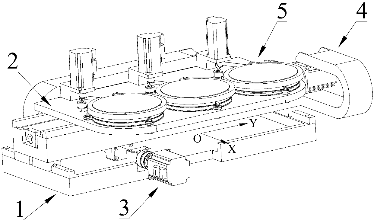
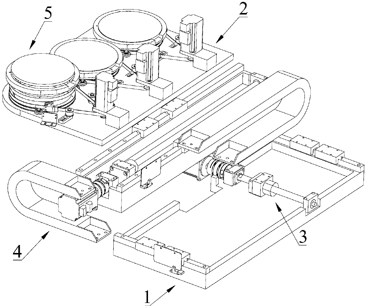
[0030] Please refer to Figure 1 to Figure 3 , Embodiment 1 of the present invention is:

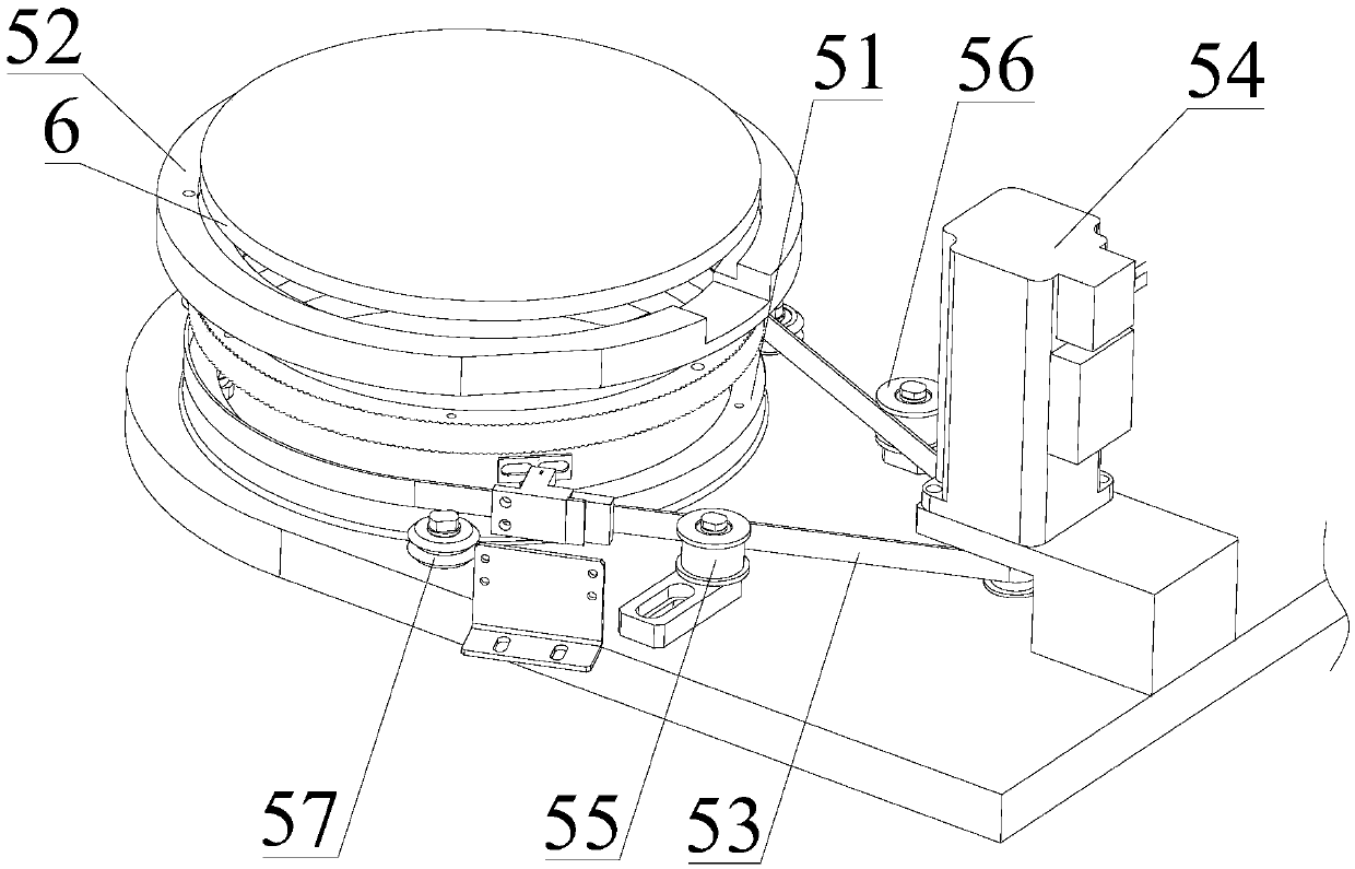
[0031] A crystal ring device such as figure 1 and figure 2 As shown, it includes a base 1, a support 2, a first drive mechanism 3 that drives the support 2 to move along the X-axis direction, and a second drive mechanism 4 that drives the support 2 to move along the Y-axis direction. The first drive mechanism 3 and the second driving mechanism 4 are fixedly arranged on the base 1 . The first drive mechanism 3 can be driven by a motor to drive the screw to drive the bracket 2 to move along the X-axis direction; the second drive mechanism 4 can be driven by a motor to drive the screw to drive the bracket 2 to move along the Y-axis direction, The guide rail can be set to play a guiding role. The crystal ring device also includes three fixing mechanisms 5 for fixing the crystal ring 6, and the three fixing mechanisms 5 are arranged at intervals on the support 2, and between two adjacent...


PUM


Abstract

The present invention discloses a crystal ring device including a bracket, a first driving mechanism for driving the bracket to move in an X-axis direction, a second driving mechanism for driving thebracket to move in a Y-axis direction, and three fixing mechanisms for fixing a crystal ring. The three fixing mechanisms are spaced apart on the bracket, the fixing mechanism includes rotating members, fixing members for fixing the crystal ring and third driving components for driving the rotating members to rotate for 360 degrees, and the fixing members are fixedly arranged on the rotating members. According to the crystal ring device, three chips of different colors can be fixed on the same piece of equipment at the same time, the crystal fixation efficiency is high, the switching of materials between machines is not needed, the time can be saved, and the crystal fixation quality can be improved.

Description

technical field [0001] The invention relates to the technical field of crystal bonding equipment, in particular to a crystal ring device. Background technique [0002] The crystal bonding machine is the key equipment in the LED packaging production line. The bonding process is as follows: the glue dispensing mechanism first dispenses glue on the crystal bonding station of the bracket, the thimble lifts the chip on the crystal ring, and then the LED chip is placed on the chip by the bonding arm. Take it out from the crystal ring blue film, and then transfer it to the crystal bonding station where the glue has been dispensed to complete the crystal bonding. [0003] Since there are three kinds of LED chips: red, green and blue, some brackets need to fix the three kinds of chips at the same time, and have the following requirements: 1. The angle of a single chip needs to be corrected before the crystal can be fixed; 2. Some chips have positive and negative electrodes at both en...

Claims


Application Information

Patent Timeline
Patent Type & Authority Applications(China)
IPC IPC(8): H01L33/48H01L21/67
CPCH01L33/48H01L21/67121
Inventor 梁国城
Owner 先进光电器材(深圳)有限公司
Why Eureka
Try Eureka