An organic electro-optic element

An electroluminescent element, organic technology, applied in electrical components, electro-solid devices, circuits, etc., can solve problems such as low efficiency

Active Publication Date: 2021-10-19
SHANGHAI BLUESHINE OPTOELECTRONICS TECH CO LTD
View PDF8 Cites 0 Cited by
  • Summary
  • Abstract
  • Description
  • Claims
  • Application Information

AI Technical Summary

Problems solved by technology

[0006] In order to solve the problems of low current efficiency and poor thermal stability of materials in the existing OLED technology, the present invention provides a high-efficiency organic electroluminescent element, which mainly solves the problem of blue OLED devices with long life and thermal stability of materials. The disadvantage of low efficiency

Method used

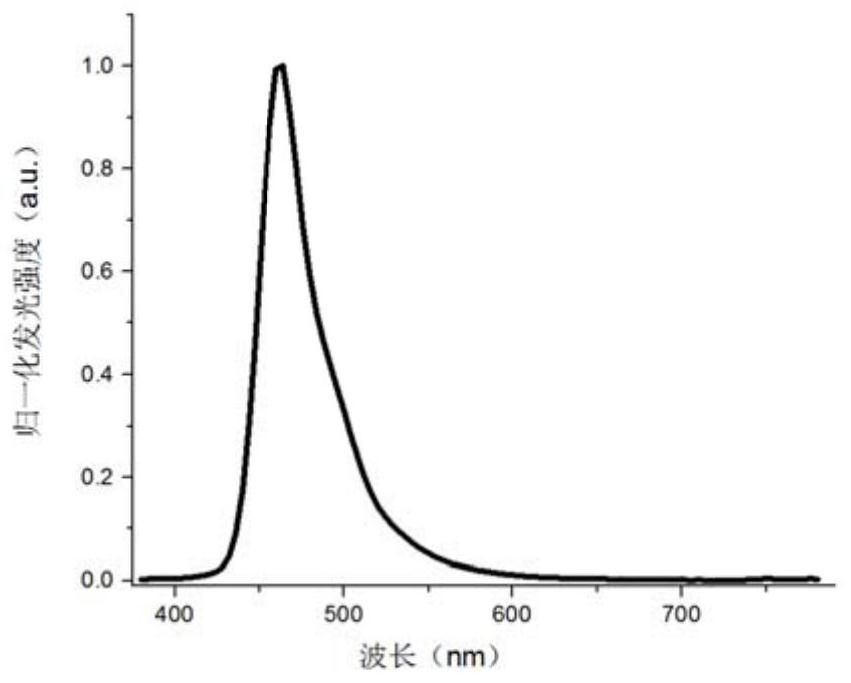
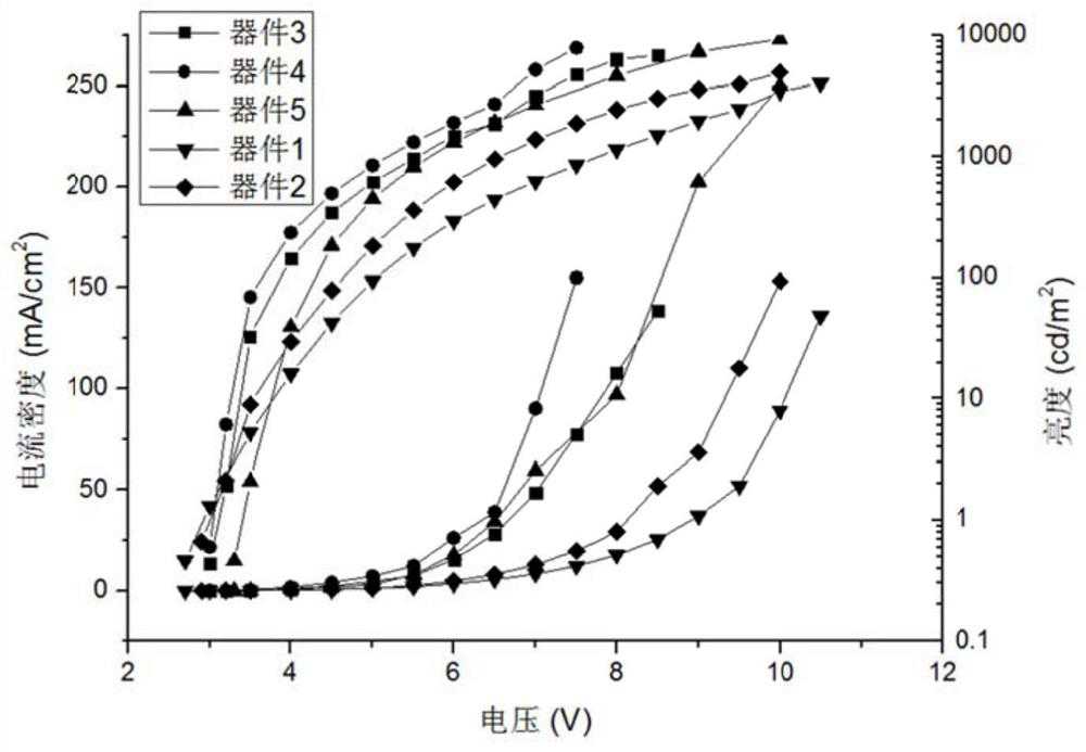
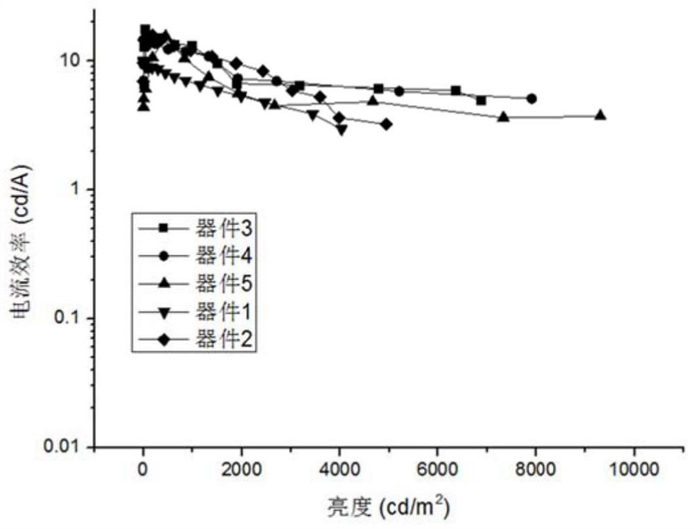

Image

  • An organic electro-optic element
  • An organic electro-optic element
  • An organic electro-optic element

Examples


Embodiment

[0068] The representative donor material or acceptor material involved in the present invention is obtained by referring to the synthesis method mentioned in the patent (CN106831581A).

[0069] General methods for the manufacture of organic electro-devices:

[0070] On the surface of the ITO glass whose luminous area is 2mm×2mm size, use the method of vacuum evaporation, spin coating, printing or printing to p-doped material P-1~P-6 or this p-doped material with 1%~50 % concentration forms the hole injection layer (HIL) of 5-50nm together with the hole transport material, then forms the hole transport layer (HTL) of 5-200nm, then forms the luminescent layer of 5-100nm on the hole transport layer ( EML), and finally form an electron transport layer (ETL) 10-200nm and a cathode 50-200nm in turn, if necessary, add an electron blocking layer (EBL) between the HTL and EML layers, and add an electron injection layer (EIL) between the ETL and the cathode Thus, an organic light emitt...


PUM

PropertyMeasurementUnit
current efficiencyaaaaaaaaaa
thicknessaaaaaaaaaa
thicknessaaaaaaaaaa

Abstract

The invention provides an organic electroluminescent element, the light-emitting layer in the organic electroluminescent element (OLED) consists of a donor material, an acceptor material, a fluorescent light-emitting material or a phosphorescent light-emitting material or a thermally delayed fluorescent material or a quantum dot A hybrid composition of luminescent materials or perovskite materials. Combining a donor material with a triplet energy level higher than 2.7eV and a glass transition temperature higher than 120 degrees with an acceptor material can obtain a high-energy intermolecular charge transfer excited state with an energy higher than 2.75eV. Through efficient anti-gap crossing and fluorescence resonance energy transfer between the excited state and the guest material, the full utilization of the singlet and triplet energy of the guest material is realized, and the obtained components have the advantages of high efficiency, low operating voltage and long service life. , can be applied to a display device or a light source device, and has good commercial application prospects.

Description

technical field [0001] The invention belongs to the technical field of organic optoelectronics, and in particular relates to an organic electroluminescence element. Background technique [0002] As a new generation of flat panel display technology, organic electroluminescence (OLED) has gradually entered people's field of vision. Its wide application prospects and rapid technological advancement in recent years have made OLED the most popular research in the field of flat panel information display and scientific research product development. one. [0003] The mechanism of OLED luminescence is that under the action of an external electric field, electrons and holes are respectively injected from the positive and negative poles and then migrate, recombine and decay in the organic material to produce luminescence. A typical structure of an OLED includes a cathode layer, an anode layer, and an organic functional layer between these two layers. The organic functional layer may i...

Claims


Application Information

Patent Timeline
Patent Type & Authority Patents(China)
IPC IPC(8): H01L51/50H01L51/54H01L51/56
CPCH10K85/624H10K50/11H10K2101/40H10K50/115H10K50/12H10K71/00
Inventor 王子兴吕瑶
Owner SHANGHAI BLUESHINE OPTOELECTRONICS TECH CO LTD
Why Eureka
Try Eureka