

Synchronization testing device and testing method of thermal barrier performance and thermal shock performance of thermal barrier coating
A thermal barrier coating, synchronous testing technology, applied in measuring devices, material thermal analysis, instruments, etc., can solve the problem of single cooling method in thermal shock test test, thermal barrier performance of thermal barrier coating and thermal shock performance cannot be tested at the same time, etc. problem, to achieve the effect of effective evaluation of spraying effect, convenient test method and accurate test
- Summary
- Abstract
- Description
- Claims
- Application Information
AI Technical Summary
Problems solved by technology
Method used
Image


Examples
Embodiment 1
[0049] The specific size of the thermal barrier coating sample is: sample shape Φ60×120mm; 4 cooling holes Φ8×120mm, the center of the hole is 9mm from the center of the sample, press figure 2 Array distribution; 4 temperature measuring holes Φ8×80mm, the center of the temperature measuring holes is 16mm, 28mm, 40mm and 52mm from the center of the sample in turn, according to figure 2 way distribution.
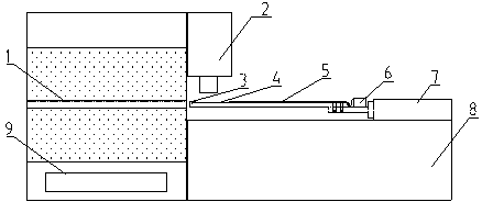
[0050] Install the ceramic plug 3 on one end of the thermal barrier coating sample, and then install the sample on the push rod 5 of the feeding mechanism, so that the cooling hole of the sample corresponds to the cooling hole in the core pipeline of the push rod 5 of the feeding mechanism The positions are consistent, and the thermocouple connected to the temperature recorder 6 is inserted into the sample temperature measurement holes 9, 12, 13, 16 through the pipeline at the center of the push rod 5 of the feed mechanism. Start the heating furnace 1, set the temperature o...
Embodiment 2
[0053] The difference between this example and example 1 is that the outer dimension of the thermal barrier coating sample is Φ48×120mm, three temperature measuring holes are set for the sample, the size of the temperature measuring holes is Φ8×80mm, and the distance between the center of the temperature measuring hole and the center of the sample is They are 16mm, 28mm, 40mm in turn, and the positions of the temperature measuring holes are respectively according to figure 2 The position distribution of temperature measuring holes 12, 13, 16.
Embodiment 3
[0055] The difference between this example and Example 1 is that the temperature of the heating furnace 1 is set to 1200°C, and the sample 4 stays in the heating furnace 1 for a set time of 10s; Cooling of the coated surface of the sample 4 by the cooling device 2 on the coated surface of the sample.
PUM
 Abstract
Description
Claims
Application Information