
Signal transmission method and devices

A technology for signal transmission and aggregation equipment, applied in the field of communications, can solve problems such as difficult implementation, multipath interference between terminal equipment and base stations, and complex engineering design, and achieve the effect of improving flexibility, reducing implementation difficulty, and simplifying engineering design.

Inactive Publication Date: 2019-04-16
DATANG MOBILE COMM EQUIP CO LTD
View PDF4 Cites 5 Cited by
  • Summary
  • Abstract
  • Description
  • Claims
  • Application Information

AI Technical Summary

Problems solved by technology

[0005] The embodiment of the present invention provides a signal transmission method and equipment, which are used to solve the problem of the transmission path from multiple remote devices to the base station in order to avoid the same coverage or overlapping coverage scenarios in the existing technical solutions for deploying indoor distribution systems. (equivalent to transmission delay) is different, the multipath interference between the terminal equipment and the base station is caused by human beings, the space requirement is high when deploying multiple remote equipment, the engineering design is complex, the implementation is difficult, and the wiring design flexibility is poor, etc. question

Method used


Image

  • Signal transmission method and devices
  • Signal transmission method and devices
  • Signal transmission method and devices

Examples


Embodiment Construction

[0051] The following will clearly and completely describe the technical solutions in the embodiments of the present invention in conjunction with the accompanying drawings in the embodiments of the present invention. Obviously, the described embodiments are only some of the embodiments of the present invention, not all of them. Based on the embodiments of the present invention, all other embodiments obtained by persons of ordinary skill in the art without making creative efforts belong to the protection scope of the present invention.

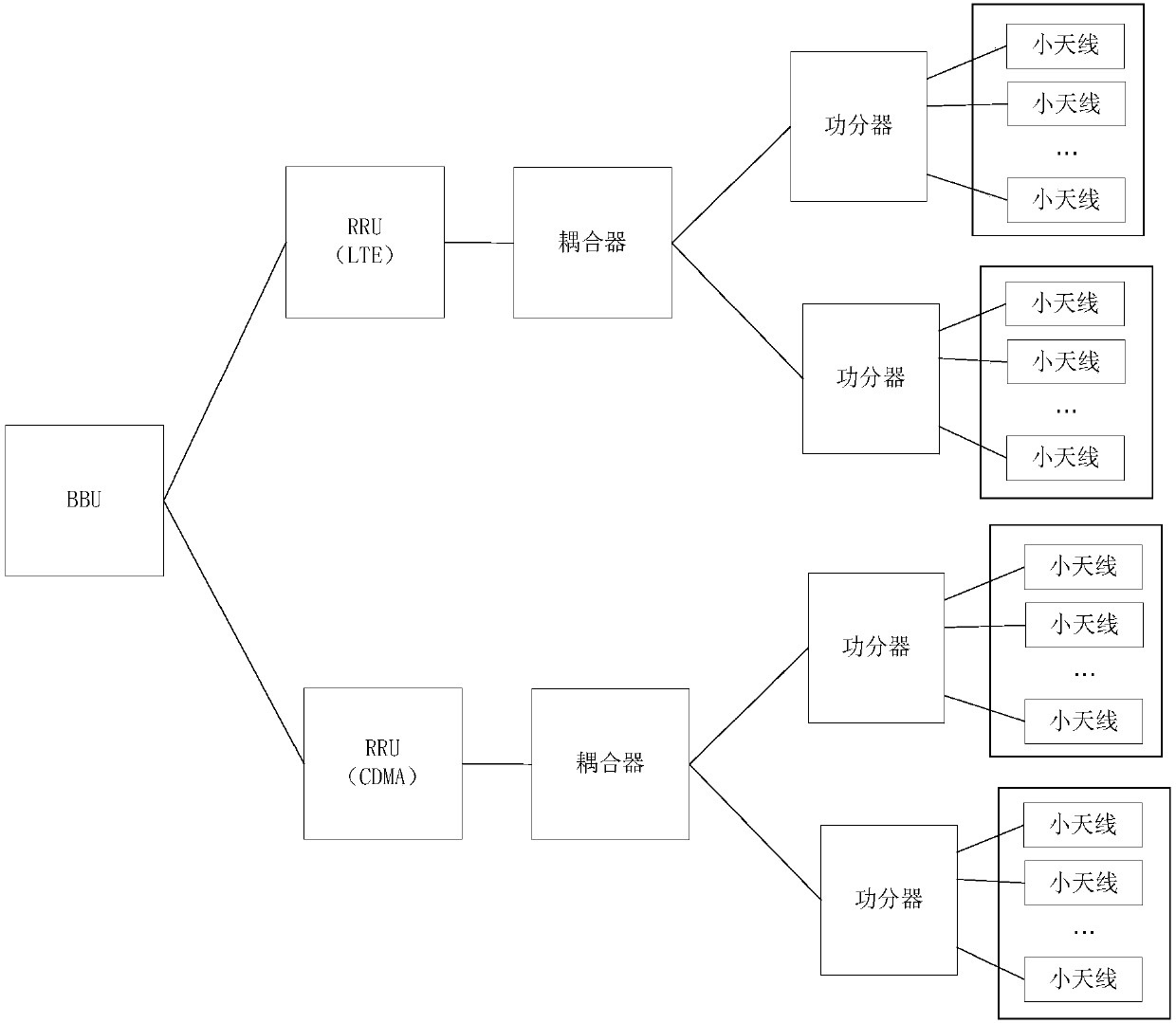
[0052] The indoor distribution system is a system that uses antenna equipment to evenly distribute the signals of network equipment in various indoor areas. This system can ensure that terminal equipment in each indoor area can access network equipment for communication. In an indoor distribution system, uplink signal transmission passes through terminal equipment, remote equipment, remote aggregation equipment, and network equipment in sequence...


PUM


Abstract

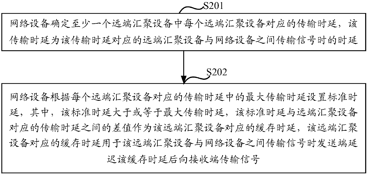
The embodiment of the invention provides a signal transmission method and devices. In the technical scheme of deploying an indoor distribution system in the prior, in order to avoid multipath interference in signal transmission of a plurality of remote devices, the problems such as high space requirements, complicated engineering design, difficult implementation, and poor wiring design flexibilityand the like exist when deploying the plurality of remote devices; and the invention is used for solving the problems. The signal transmission method comprises the following steps: a network device determines a transmission delay corresponding to each remote aggregation device of at least one remote aggregation device; and the network device sets a standard delay according to the maximum transmission delay in the transmission delay corresponding to each remote aggregation device, wherein the difference between the standard delay and the transmission delay corresponding to the remote aggregation device is used as a buffer delay of the remote aggregation device, and the buffer delay corresponding to the remote aggregation device is used by a sending end to delay the buffer delay and then transmit a signal to a receiving end when the signal is transmitted between the remote aggregation device and the network device.

Description

technical field [0001] The present invention relates to the field of communication technology, in particular to a signal transmission method and equipment. Background technique [0002] The indoor distribution system is a system that evenly covers the signal of network equipment to each indoor area through remote equipment, remote aggregation equipment and other equipment. In an indoor distribution system, uplink signal transmission passes through terminal equipment, remote equipment, remote aggregation equipment, and network equipment in sequence. Multiple remote equipment can be connected to the same remote aggregation equipment, and multiple remote aggregation equipment can be connected to the same Network device connection. [0003] In the indoor distribution system, the signal coverage of multiple remote devices may overlap. Take the uplink signal transmission as an example. In the overlapping area of ​​the signal coverage of multiple remote devices, the uplink signal ...

Claims


Application Information

Patent Timeline
Patent Type & Authority Applications(China)
IPC IPC(8): H04W16/20H04W56/00H04J11/00
CPCH04J11/0063H04W16/20H04W56/00
Inventor 李庆华马亮
Owner DATANG MOBILE COMM EQUIP CO LTD
Learn More