

Air conditioning device
An air conditioning and control device technology, which is applied to the control input involving air characteristics, space heating and ventilation, space heating and ventilation control input, etc. Flying, comfort-enhancing effect
- Summary
- Abstract
- Description
- Claims
- Application Information
AI Technical Summary
Problems solved by technology
Method used
Image

Examples
Embodiment approach 1
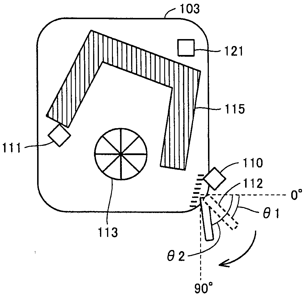
[0031] (Structure of Air Conditioning Device 101)
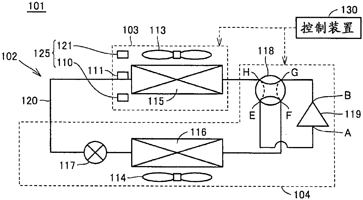
[0032] figure 1 It is a figure which shows an example of the air-conditioning apparatus 101 in Embodiment 1 of this invention. Such as figure 1 As shown, the air conditioner 101 includes an indoor unit 103 , an outdoor unit 104 , and a control device 130 .
[0033] The indoor unit 103 includes an indoor blower 113 , an indoor heat exchanger 115 , an infrared sensor 110 , a piping temperature sensor 111 , and an indoor temperature sensor 121 . The outdoor unit 104 includes an outdoor blower 114 , an outdoor heat exchanger 116 , an expansion valve 117 , a four-way valve 118 and a compressor 119 . The refrigerant circuit 102 is configured by connecting the outdoor heat exchanger 116 , the expansion valve 117 , the four-way valve 118 , the compressor 119 , and the indoor heat exchanger 115 in a ring shape by the refrigerant piping 120 . A heat pump is formed by circulating a refrigerant in the refrigerant circuit 102 while re...
Embodiment approach 2
[0091] Embodiment 2 of the present invention will be described below. The air-conditioning apparatus according to Embodiment 2 includes a control device for controlling a plurality of indoor units 103 to make the indoor temperature of the air-conditioning target space R a target temperature. Since the control of the load detection means, temperature detection means, air blowing control means, and air direction control means of each indoor unit 103 is the same as that of Embodiment 1, illustration and description are omitted.
[0092] Figure 11 It is a figure which shows an example of the control system in Embodiment 2. The indoor units 103A, 103B, and 103C are connected to the centralized control device 230 through communication devices 203 , 204 , and 205 , respectively. The indoor units 103A, 103B, and 103C can be controlled from the centralized control device 230 . The connection between the indoor units 103A, 103B, 103C and the communication devices 203, 204, 205 and t...
PUM
 Abstract
Description
Claims
Application Information