Image formation device

An image and separation device technology, applied in the direction of electric recording process applying charge pattern, electric recording process applying electric charge pattern, equipment of electric recording process applying electric charge pattern, etc. range, inability to improve carrier fluid resistivity, etc.

Inactive Publication Date: 2019-04-16
CANON KK
View PDF1 Cites 0 Cited by
  • Summary
  • Abstract
  • Description
  • Claims
  • Application Information

AI Technical Summary

Problems solved by technology

Therefore, in the past, based on the detection value of the resistance sensor which is also affected by other than the charge control agent, even if the carrier liquid for replenishment is supplied to the carrier tank, the resistivity of the carrier liquid cannot be improved. The resistivity is maintained within the specified range

Method used


Image

  • Image formation device
  • Image formation device
  • Image formation device

Examples


no. 1 approach

[0023] use Figure 1 to Figure 7 A first embodiment of the present invention will be described. First, use figure 1 A schematic configuration of the image forming apparatus of this embodiment will be described.

[0024] [Image forming device]

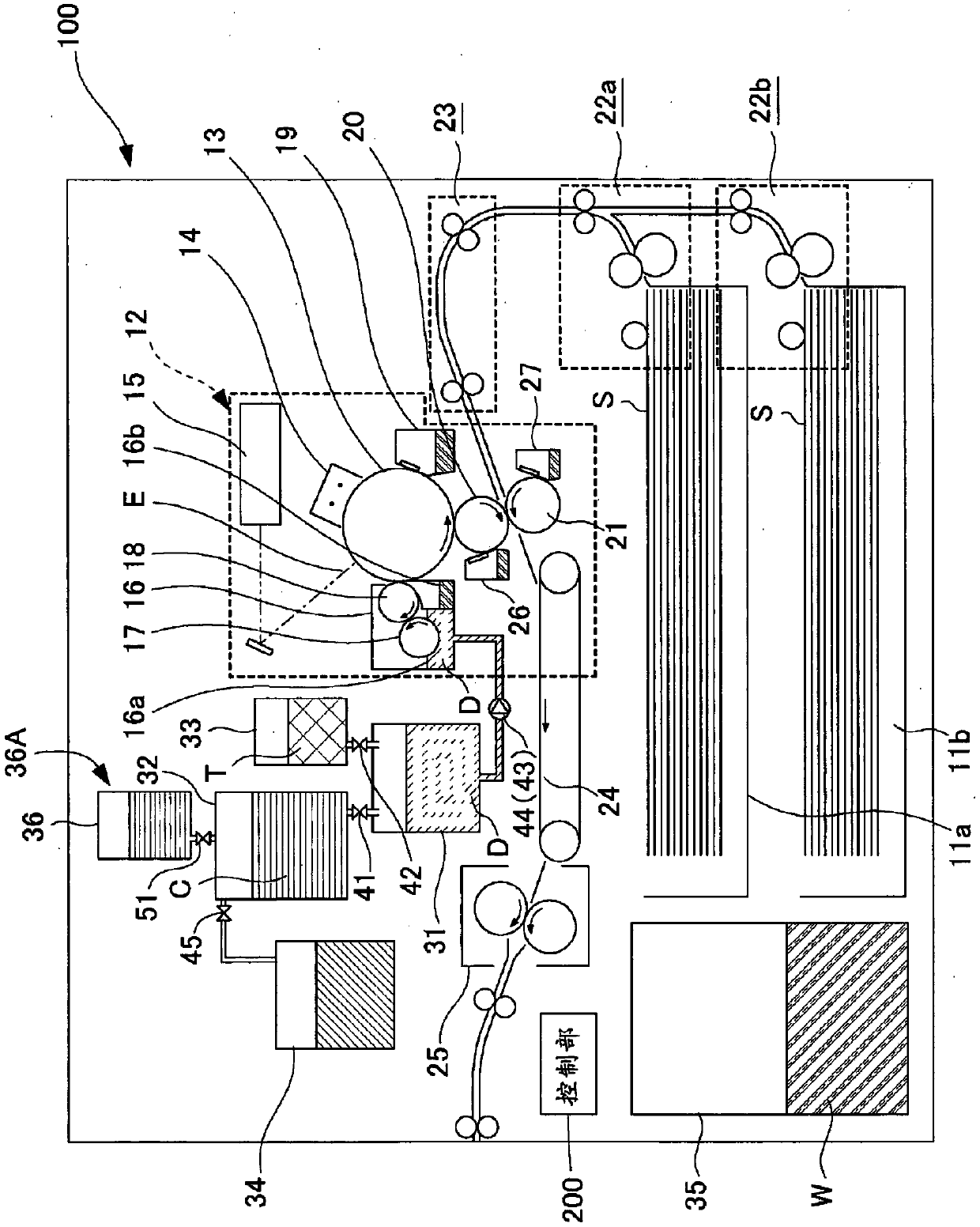
[0025] The image forming apparatus 100 of the present embodiment is an electrophotographic digital printer that forms a toner image on a recording material S (sheet material such as paper or OHP sheet). The image forming apparatus 100 operates based on an image signal, and transfers a toner image formed by the image forming unit 12 to a recording material S that is sequentially conveyed from the cartridges 11a and 11b, and then fixes it to obtain an image. The image signal is transmitted to image forming apparatus 100 from a scanner not shown, an external terminal such as a personal computer, and the like.

[0026] The image forming unit 12 includes a photosensitive drum 13 as an image carrier, a charger 14 , a laser exposure device...

no. 2 approach

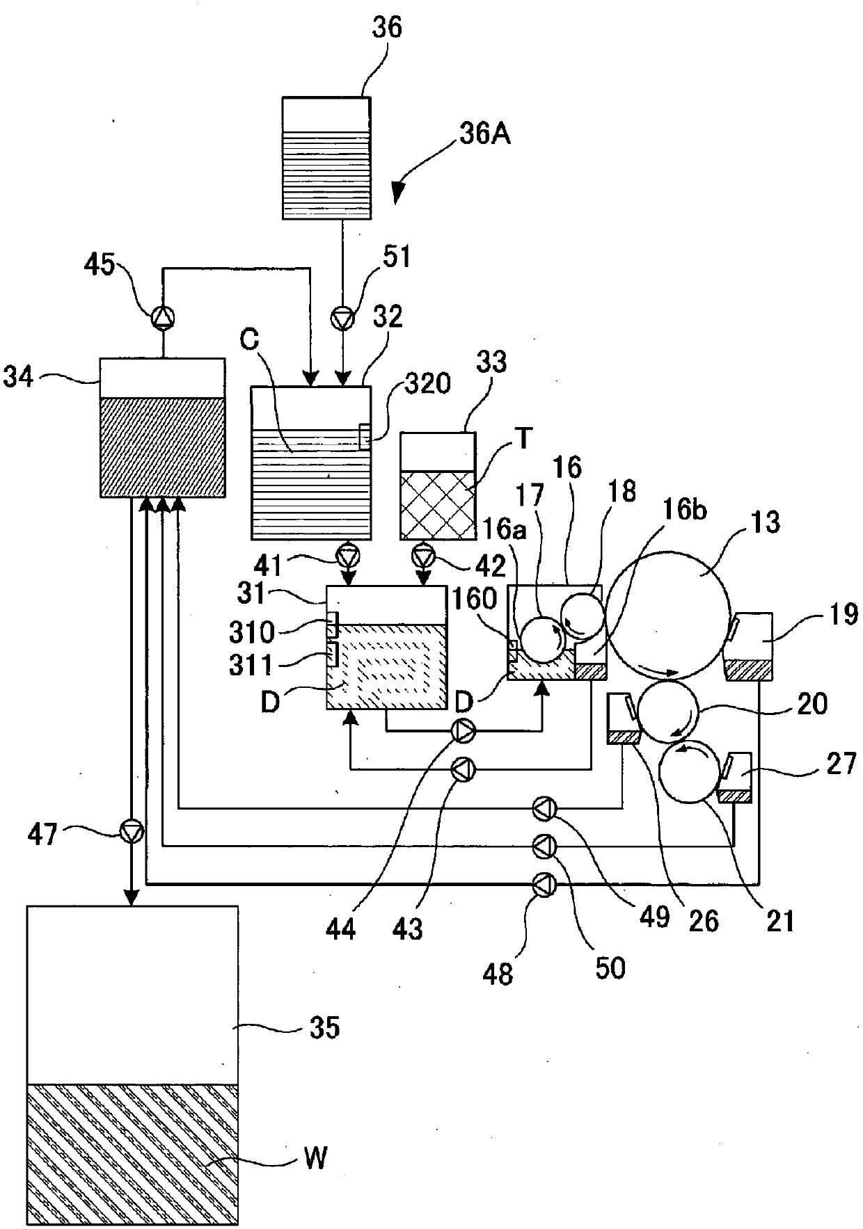
[0120] use Figure 10 A second embodiment will be described. In the first embodiment described above, the carrier liquid for replenishment is supplied to the carrier tank 32 from the replenishment device 36A. In contrast, in the image forming apparatus 100A of the second embodiment, the carrier liquid for replenishment is supplied from the replenishment device 60A to the mixer 31 . Since other basic structures and functions are the same as those of the above-mentioned first embodiment, description and illustration of the same structure will be omitted or simplified below, and the description will focus on the parts different from those of the first embodiment.

[0121] In the case of the present embodiment, a separation and extraction device 34 , a carrier tank 32 containing the carrier liquid separated by the separation and extraction device 34 , and a mixer 31 to which the carrier liquid is supplied from the carrier tank 32 are provided. In addition, in the present embodim...

Embodiment approach

[0124] In addition, when the carrier liquid for replenishment is replenished, it is only necessary to add the replenished amount to the "liquid amount passed zero times" in the first row and first column of the matrix C. Thereafter, using the matrix C to which the replenishment amount has been added, the calculation of "the liquid amount per number of passes" is performed as described above. by Figure 6 To briefly describe as an example, in the case where, for example, 20 ml of carrier fluid for replenishment is replenished after the second pass, the value in the first row and first column of matrix C is changed from "25" to "20" with the replenishment amount added. "45" after.

[0125] Conversely, when the carrier liquid is consumed during development, it is only necessary to subtract the liquid amount obtained by dividing the consumption evenly from each element of the matrix Q. Thereafter, using the matrix Q after subtracting the consumed amount, the calculation of "the ...


PUM


Abstract

A computation unit (300) finds the resistivity of a carrier liquid in a carrier tank by computation. A resistivity computation unit (302) finds the resistivity of the carrier liquid on the basis of "the liquid quantity for each number of times of passage of the carrier liquid that has passed through a separation and extraction device" and "the resistivity for each number of times of passage of thecarrier liquid that has passed through the separation and extraction device". "The liquid quantity for each number of times of passage" is computed by a deterioration degree distribution computationunit 301 and stored in a memory (201). Regarding "the resistivity for each number of times of passage", the resistivity of the carrier liquid after the carrier liquid has passed through the separationand extraction device is prestored in the memory (201) for each number of times of passage. A carrier replenishment determination unit (202) determines, on the basis of the found resistivity of the carrier liquid, whether a replenishment carrier liquid is replenished or not. A control unit (200) controls a replenishment pump (51) on the basis of the determination.

Description

technical field [0001] The present invention relates to an electrophotographic image forming apparatus that forms an image using a liquid developer. Background technique [0002] Conventionally, there is known an image forming apparatus that forms an image using a liquid developer containing toner and a carrier liquid. The liquid developer is accommodated in a mixer, and is supplied from the mixer to a developing device for development. Then, the toner for replenishment is contained in the toner tank, the carrier liquid for replenishment is contained in the carrier tank, respectively, and the toner for replenishment and the carrier liquid for replenishment are replenished from the respective tanks to the mixer. The mixer mixes and disperses the toner in the carrier liquid, thereby producing a liquid developer. In such an image forming apparatus, liquid developer not used for development is recovered and recycled. In the recycling of the liquid developer, the toner as the ...

Claims


Application Information

Patent Timeline
Patent Type & Authority Applications(China)
IPC IPC(8): G03G15/10
CPCG03G15/105G03G2215/0626G03G2215/0658G03G15/104G03G15/10G03G9/12G03G13/10
Inventor 田中颂二
Owner CANON KK
Why Eureka
Try Eureka